5
3.0 OPERATION
3.1 Firmware Version
The GFM is supplied with a plug-in the wall transformer, which powers the GFM
and will also charge the optional internal battery. Plug the transformer into a suitable
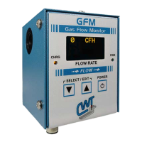
ac receptacle, and connect the power cable into the "POWER" jack located on the
bottom panel of the GFM. Press the power switch on the front panel "ON". The
“POWER” LED will light and the following power up message will be displayed:
**** GFM ****
P/N A5Z0044 Ver #.##
Copyright (c) 2011
Computer Weld
Technology Inc.
All Rights Reserved
Where: #.# is the firmware version number
Followed by the run time display:
0 CFH
Note: CFH will be replaced with LPH in metric mode
Activate the gas solenoid for the welding torch. The GFM will now display the gas
flow rate in CFH (Cubic Feet per Hour) or LPM (Liters per Minute).
3.2 Program Limits
To program the High/Low limits and test parameters press both “▼” and "▲" switch
simultaneously to enter the “Select Para INC/DEC” mode. The first programmable
parameter will appear on the display. To increment through the program menus
press the “▲” button. To decrement through the menus press the “▼” button. To
edit a menu option press both “▼” and "▲" switch simultaneously to enter the “Edit
Para INC/DEC” mode. To increment the parameter press the “▲” button. To
decrement the parameter press the “▼” button. To end the “Edit Para INC/DEC”
press both “▼” and "▲" switch simultaneously to exit and return to the normal display
mode. The user can edit only one parameter at a time. To edit other parameters
repeat the above sequence.
 Loading...