14
8.0 POWER OPTIONS AND BATTERY SPECIFICATION/CHANGING
8.1 Power Options
The GFM can be used as a Battery Powered device or installed in-line and
powered from a Plug-in Wall power supply or user supplied 12 - 24 vdc power
supply.
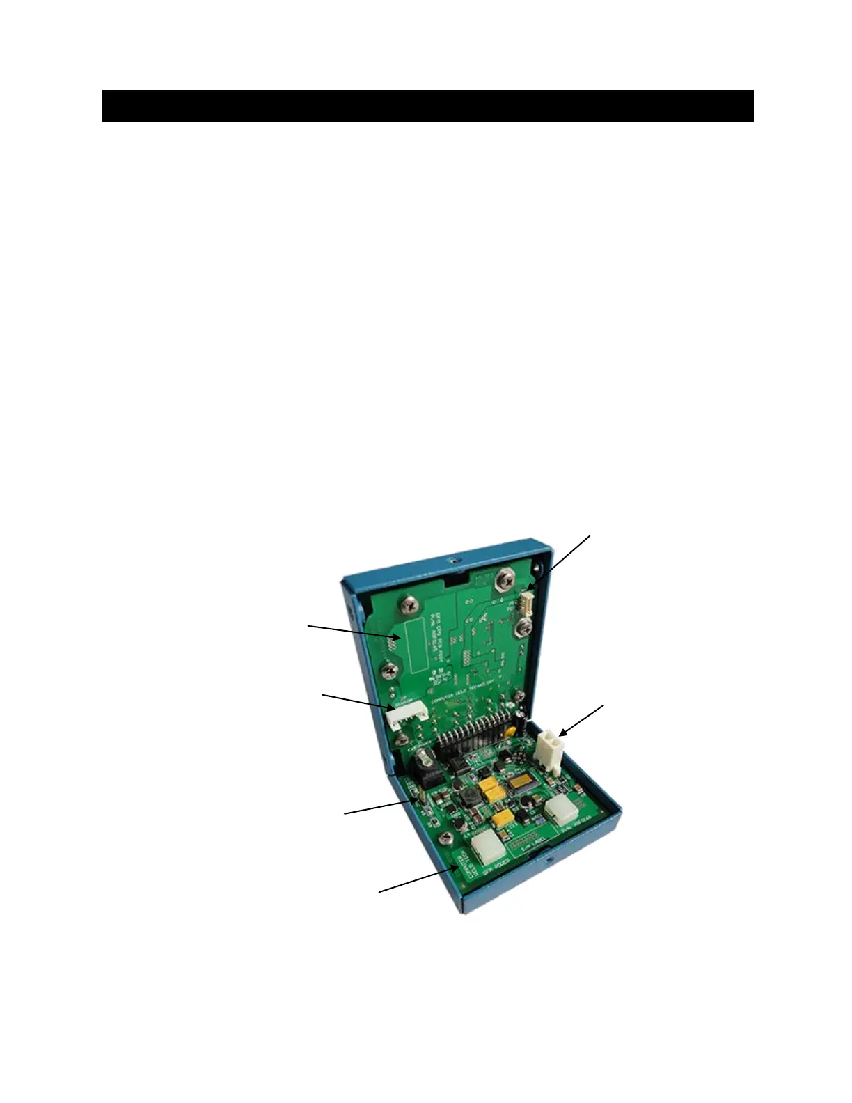
8.1.1 Power Board – Revision: 0
By default the jumper on Header “JP1” is installed for “Manual” function.
This will enable the power switch whenever the battery is being used as
the power source.
To enable the “Auto Power Up” function, a jumper must be removed on
Header “JP1”. This disables the power switch for whenever the external
power is applied through the Power Connector or Aux Connector keeping
the GFM always turned on.
Inside View of GFM Enclosure
(Power Board - Revision: 0)
“J7”
 Loading...