15
8.1.2 Power Board – Revision: A
By default the jumper on Header “JP1” is installed on Location “A” for
“Manual” function. This will enable the power switch whenever the battery
is being used as the power source.
When the jumper is on Location “B”, this sets the “Auto” function. This
disables the power switch for whenever the external power is applied
through the Power Connector or Aux Connector keeping the GFM always
turned on.
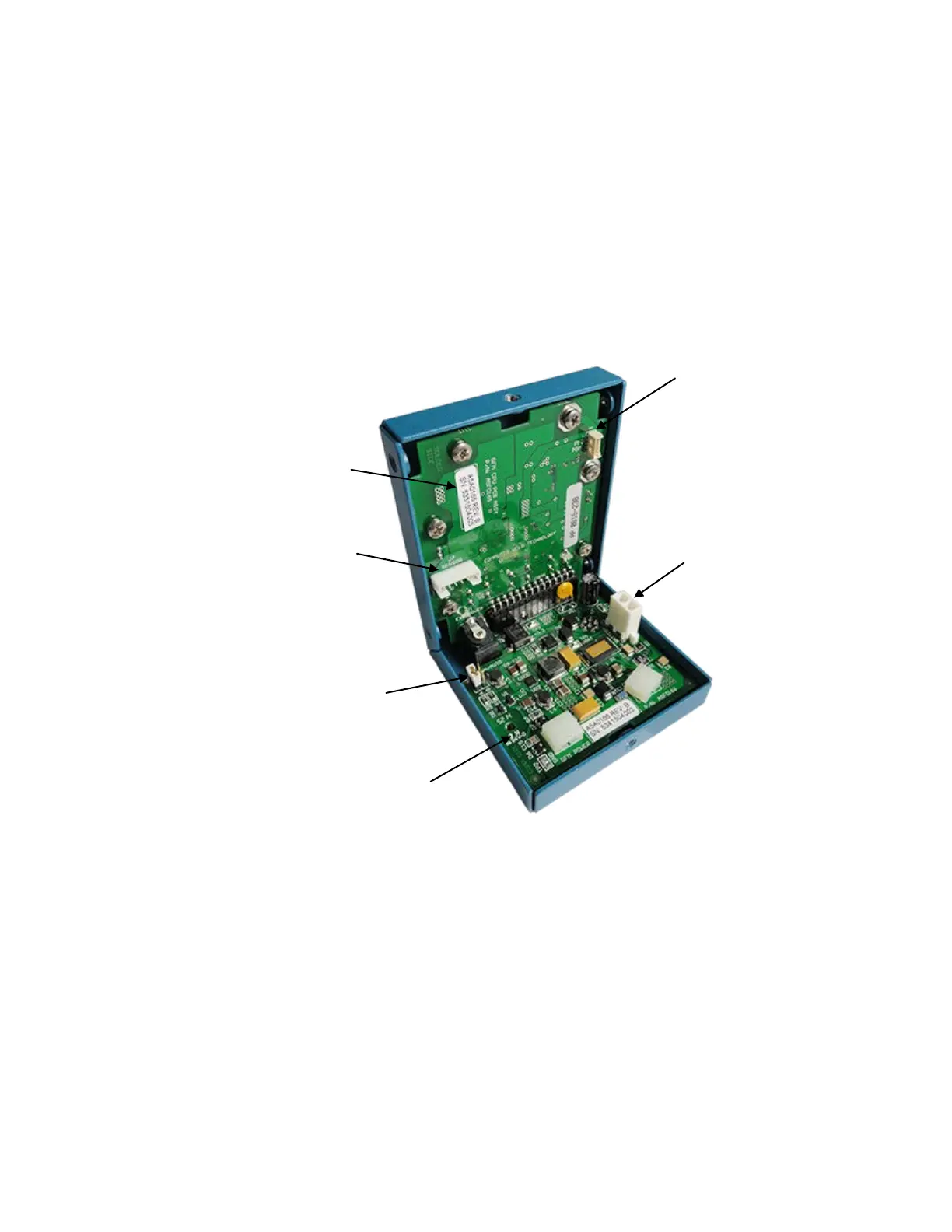
Inside View of GFM Enclosure
(Power Board - Revision: A)
“J7”
 Loading...