2. Remove the four retaining screws of the cable protection cover then remove the cover.
3. unplug cable connectors.
4. Pull out the old battery pack and replace new one.
Reassemble the retaining screws, covers, black and red cable, and front panel in the reverse sequence of the above steps. Recharge the
unit for 4-8 hours to ensure maximum UPS battery runtime.
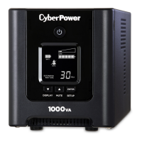
LCD STATUS DEFINITION
INPUT voltage meter: This meter measures the AC voltage that the UPS system is receiving from the utility wall outlet. The INPUT voltage
readout can be used as a diagnostic tool to identify poor-quality input power. The AVR in this UPS continuously conditions the power to a
stable 110/120V output to connected equipment. In the event of a complete power loss, severe brownout, or over voltage, the UPS relies on
its internal battery back up to supply a consistent 110/120V output.
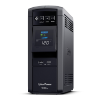
OUTPUT voltage meter:
This meter measures in real time, the AC voltage that the UPS system is providing to the computer, such as normal line mode, AVR mode
and battery back up mode.
Note:
The OUTPUT voltage readout displays the status of the battery back up outlets.
ESTIMATE RUN TIME:
This displays the run time estimate of the UPS with the current battery capacity
and load.
NORMAL icon:
This icon appears when the UPS is working under normal conditions.
BATTERY icon:
During a severe brownout or blackout, this icon appears and an alarm sounds (two short beeps followed by a pause) to indicate the UPS is
operating from its Internal batteries. During an extended brownout or blackout that drains the battery, a continuous alarm will sound (and the