25
Wireless Receiver Installation Considerations - continued
Using The TBUS - No Length Limits and Better Receiver Performance
While using the modular jack is a perfectly acceptable installation, receiver placement is limited
to no more than 14 feet from the Command Station. However, finding the best receiver
performance location is easier if the coaxial TBUS cable is used. Using the coax cable TBUS
instead of modular allows placement of the receiver almost anywhere. The next hookup diagram
shows te receiver connected somewhere along the coaxial TBUS.
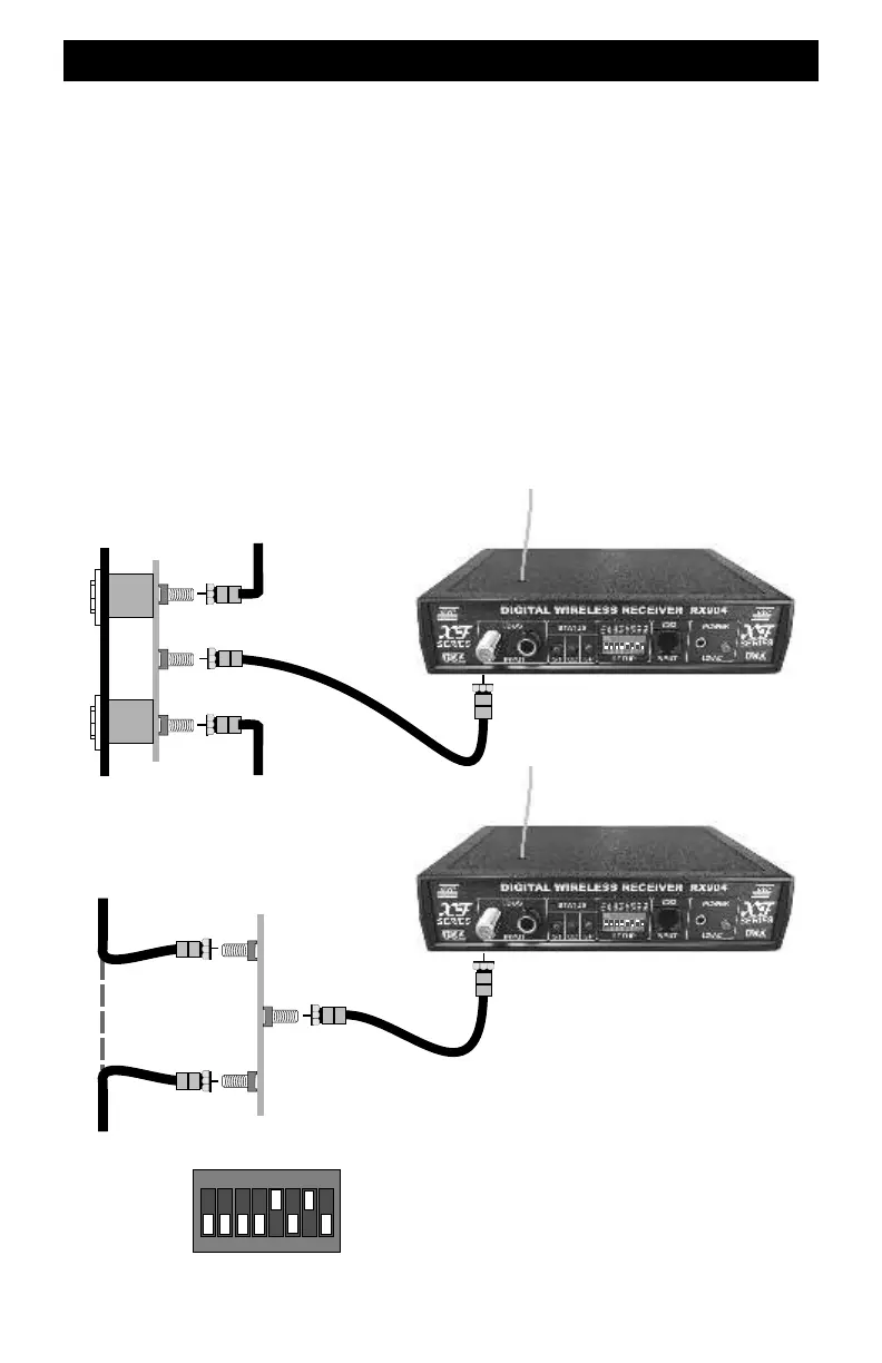
If the receiver is close to an existing plug-in throttle fascia plate, just solder a 3rd F-Jack into the
holes on the circuit board. F-jacks can be purchased from CVP Products. The receiver must not
be at the end of the coax run. If its at the end of the run, see the next section.
If the desired location is further than a few feet from an existing fascia plate, install a Fascia-Tee
board, also available from CVP. This is nothing more than a fascia circuit board without the 1/4
inch throttle jacks. Cut the TBUS coax cable, attach twist-on connectors and connect them to the
Fascia Tee board. The maximum length for the coax from the T-board to the receiver is about 3
feet. Any longer and the signal becomes distorted and unusable by the Command Station. In the
illustrations below, the 12VAC transformer is not shown.
Existing Fascia Plate
Added F-Jack
Max length is 3 feet
New Fascia-Tee Board
Max length is 3 feet
X
ON
1 2
3
4
5 6
7
8
RX904 switch setting for using the TBUS jack with
receiver not at the end of the coax TBUS. Switch number
8 is OFF.