26
Wireless Receiver Installation Considerations - continued
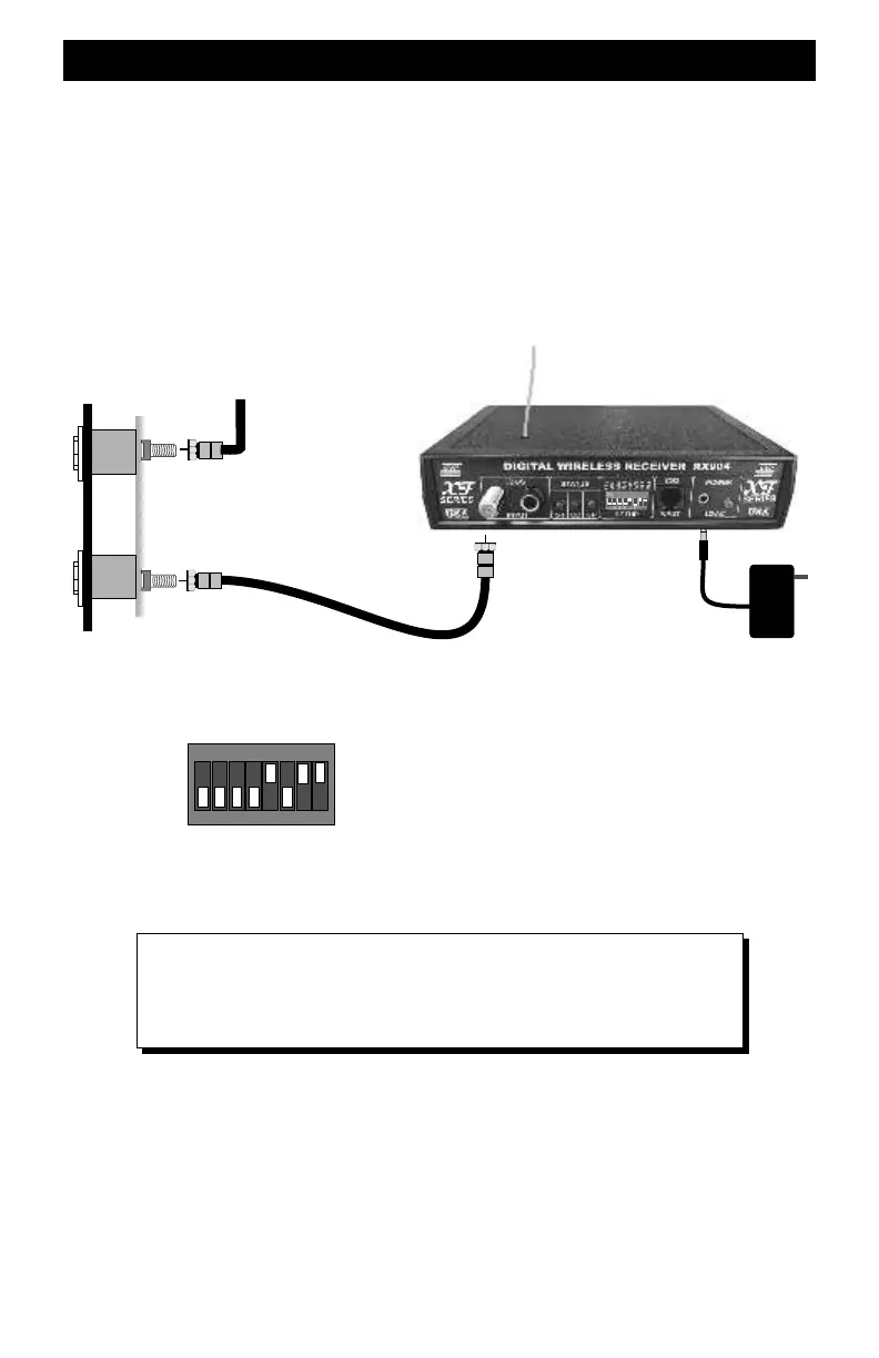
Adding A Wireless Receiver At The End of the TBUS Coax Cable Run
This hookup diagram is for use when the wireless receiver is at the end of the TBUS coaxial
cable run.
For this hookup, if you have already installed the 75 ohm terminating resistor soldered to the last
fascia plate, it needs to be removed. The wireless receiver includes a 75 ohm resistor which can
be turned on with switch 8.
Once the old terminating resistor has been removed, attach the coax cable to the fascia-plate F-
jack and the F-jack on the receiver. The overall length of the entire length of coax should be no
more than about 100 feet for RG58 or RG59 coax. If you have used RG6, the total overall length
can be twice as long.
Last fascia plate and
end of coax cable run
12VAC Transformer
ON
1 2
3
4
5 6
7
8
WARNING
Never use any type of inline amplifier, TV splitter or TV “Y” adapters.
They will not work and may damage the Extender.
RX904 switch setting for using the TBUS jack with
receiver at the end of the coax TBUS. The terminator
switch #8 is ON.