EN / CZone® Control X User & Installation Manual
MOUNTING
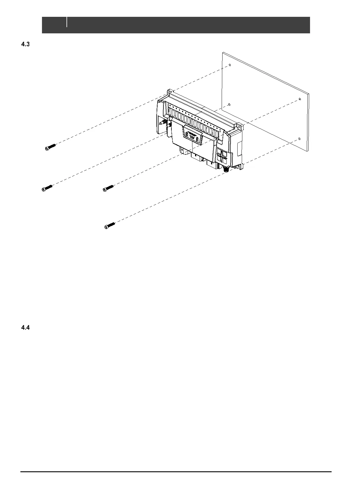
Figure 6. Mounting Screw Locations
1. Place Control X on a solid flat surface. Mark the lower screw locations.
2. Remove Control X and partially install lower screws using 10G (5mm) self-tapping screws or bolts.
3. Slot the Control X on to the bottom screws and install upper retaining screws.
4. Torque down each mounting screw, 6Nm max.
5. Ensure enough space is left below the Control X to easily install cable connectors and access for
maintenance.
PLANNING
Make a list of all inputs and outputs to be wired to the Control X and take note of the output channel ratings and functions
as shown in Figure 7 and Figure 8. Assign each input and output to a channel on the Control X ensuring loads are wired
to the appropriate channel for the functionality required.
• All high-side output channels have the option to alarm on detection of external voltage, useful for circuits such
as Bilge Pumps with an external or “automatic” supply from a float switch. This feature reduces wiring by
allowing control and feedback from a single wire.
• For loads with a continuous current exceeding max channel current, it is possible to parallel high-side or low-
side output channels.
• Maximum module current must be taken into consideration:
o Control X PLUS – 120A
o Control X – 100A
• Maximum current for each connector must be taken into consideration:
o Connector A – 50A (Control X PLUS Only)
o Connector B – 80A
o Connector C – 30A (Control X PLUS), 20A (Control X)