EN / CZone® Control X User & Installation Manual
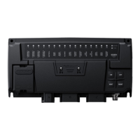
CIRCUIT LABELING
Figure 12. CZone Control X Labeling
Label the Circuits
• The Control X is supplied with labels to fit into the indentations under each circuit LED indicator.
• Custom label sets can be ordered for a more complete finish in OEM installations.
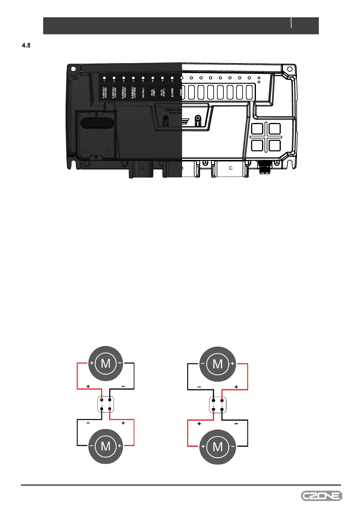
5 H-Bridge Motor Control
2 x 15A H-Bridge channels are included on the Control X PLUS allowing reversing motors to be connected directly to
the module. The channels are available on Plug A. A combination of 1x H-Bridge output and 2x single channel outputs,
or 2x H-Bridge outputs can be configured.
Motor polarity for each of the H-Bridge outputs for forward and reverse is shown below:
Pin 1 = Positive
Pin 3 = Positive
Pin 4 = Negative
Pin 1 = Negative
Pin 2 = Positive
Pin 3 = Negative
Pin 4 = Positive
Figure 13. H-Bridge Direction Polarity Diagram