When there is reception or
transmission (i.e. Activity—Act) of
data occurring at a 1000Mbps
Ethernet connected port.
Rear Panel Description
The rear panel of the Switch contains an AC power connector. The AC power connector is a standard three-
pronged connector that supports the power cord. Plug-in the female connector of the provided power cord
into this socket, and the male side of the cord into a power outlet. The Switch automatically adjusts its power
setting to any supply voltage in the range from 100 to 240 VAC at 50 to 60 Hz. Connect the Kensington-
compatible security lock, at the rear of the switch, to a secure immovable device. Insert the lock into the
notch and turn the key to secure the lock.
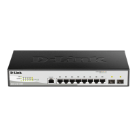
DGS-1210-10/ME
Figure 1.7 - DGS-1210-10/ME rear panel
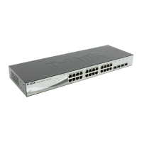
DGS-1210-20/ME
Figure 1.8 - DGS-1210-20/ME rear panel
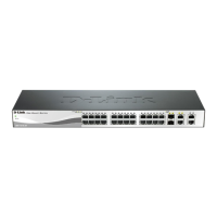
DGS-1210-28/ME
Figure 1.9 - DGS-1210-28/ME real panel
DGS-1210-28P/ME
Figure 1.10 -DGS-1210-28P/ME real panel
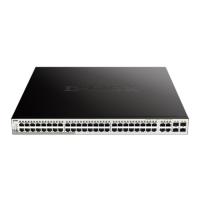
DGS-1210-52/ME
Figure 1.11 -DGS-1210-52/ME real panel
 Loading...