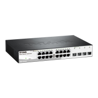
EasyManua.ls Logo

D-Link DGS-1210/ME series - Appendix B -Cables and Connectors

D-Link DGS-1210/ME series
52 pages
To Next Page IconTo Next Page
To Previous Page IconTo Previous Page
Loading...
DGS-1210/ME series Metro Ethernet Switch Hardware Installation Guide
2
2
7
7
Appendix B Cables and Connectors
Ethernet Cable:
When connecting the Switch to another switch, a bridge or hub, a normal cable is necessary. Please review
these products for matching cable pin assignment.
The following diagrams and tables show the standard RJ-45 receptacle/connector and their pin assignments.
Figure D- 1. The standard RJ-45 port and connector
RJ-45 Pin Assignments
Contact
MDI-X Port
MDI-II Port
1
RD+ (receive)
TD+ (transmit)
2
RD- (receive)
TD- (transmit)
3
TD+ (transmit)
RD+ (receive)
4
1000BASE-T
1000BASE-T
5
1000BASE-T
1000BASE-T
6
TD- (transmit)
RD- (receive)
7
1000BASE-T
1000BASE-T
8
1000BASE-T
1000BASE-T

Other manuals for D-Link DGS-1210/ME series

Related product manuals