2
ENGLISH
About This Guide
This guide gives step-by-step instructions for setting up
switches and relative Warranty, Safety, Regulatory, and
Environment Notice. Please note that the model you
have purchased may appear slightly different from those
shown in the illustrations.
For more detailed information about your switch, its
components, making network connections, and technical
specications, please refer to the User’s Guide included
with your switch.
Step 1 – Unpacking
Open the shipping carton and carefully unpack its
contents. Please consult the packing list located in the
User Guide to make sure all items are present and
undamaged. If any item is missing or damaged, please
contact your local D-Link reseller for replacement.
- One D-Link Switch
- Rack mounting bracket
- Rubber Feet
- Power cord
- One console cable
- Power cord retainer
- User’s Guide CD with DNA (D-Link Network Assistant)
program
- One multilingual Getting Started Guide
- An accessory kit for one ground screw
Step 2 – Switch Installation
For safe switch installation and operation, it is
recommended that you:
• Visually inspect the power cord to see that it is secured
fully to the AC power connector.
• Make sure that there is proper heat dissipation and
adequate ventilation around the switch.
• Do not place heavy objects on the switch
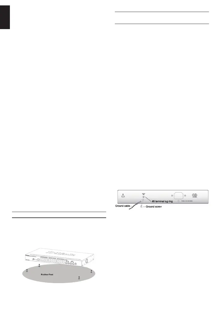
Desktop or Shelf Installation
When installing the switch on a desktop or shelf, the
rubber feet included with the device must be attached
on the bottom at each corner of the device’s base. Allow
enough ventilation space between the device and the
objects around it.
Figure 1. Attaching the rubber feet
Grounding the Switch (depending on
the purchased model)
This section describes how to connect the Switch to
ground. You must complete this procedure before
powering on your Switch.
Required Tools and Equipment
• Grounding screws (included in the accessory kit):
One M4 x 6 mm (metric) pan-head screw
• Grounding cable (not included in the accessory kit):
The grounding cable should be sized according
to local and national installation requirements.
Depending on the power supply and system, a
12 to 6 AWG copper conductor is required for
installation. Commercially available 6 AWG wire is
recommended. The length of the cable depends
on the proximity of the Switch to proper grounding
facilities.
• A screwdriver (not included in the accessory kit)
You can connect the Switch to a protective ground by
following the steps below:
1. Verify if the system power is off.
2. Use the grounding cable to place the #8 terminal
lug ring on top of the ground-screw opening.
3. Insert the grounding screw into the ground-screw
opening.
4. Using a screwdriver, tighten the grounding screw to
secure the grounding cable to the Switch.
5. Attach the terminal lug ring at the other end of the
grounding cable to an appropriate grounding stud or
bolt on rack where the Switch is installed.
6. Verify if the connections at the ground connector on
the Switch and the rack are securely attached.
Figure 2. Connect a Grounding Cable
 Loading...