4
ENGLISH
Step 2
In order to login and congure the switch via an Ethernet
connection, the PC must have an IP address in the same
range as the switch. For example, if the switch has an
IP address of 10.90.90.90, the PC should have an IP
address of 10.x.y.z (where x/y is a number between 0 ~
254 and z is a number between 1 ~254), and a subnet
mask of 255.0.0.0.
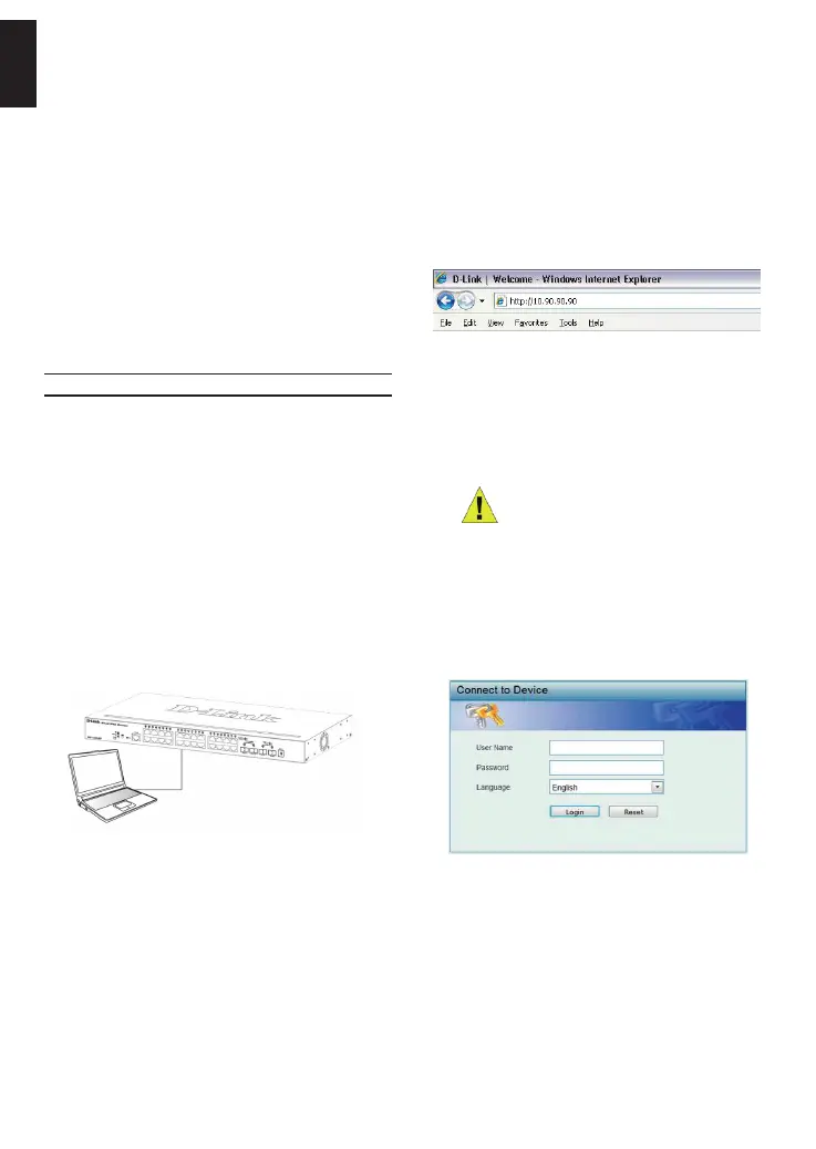
Open your web browser and enter http://10.90.90.90
(the factory-default IP address) in the address box. Then
press <Enter>.
Figure 8. Enter the IP address 10.90.90.90 in the web
browser
The web conguration can also be accessed through the
DNA. You can click the IP hyper link in the device list in
the DNA to open the web GUI of devices.
NOTE: The switch’s factory default IP
address is 10.90.90.90 with a subnet
mask of 255.0.0.0 and a default
gateway of 0.0.0.0
Step 3
When the following logon dialog box appears, enter
“admin” for both the Username and Password and
choose the language of the Web-based Management
interface then click Login.
Figure 9. Enter Network Password window
Step 4
Before entering the Web-based Management, the
Smart Wizard will guide you to quickly congure some
functions, such as Ip Information, User Account and
SNMP Settings. If you don’t plan to change anything,
click Exit to exit the Wizard and enter the Web-based
Management. For a detailed look at the Smart Wizard’s
functions, please refer to the Smart Wizard introduction
in the user manual.
Power Failure
As a precaution, the switch should be unplugged in
case of power failure. When power is resumed, plug the
switch back in.
Management Options
This system may be managed out-of-band through the
console port on the front/back panel or in-band using
Telnet. The user may also choose the web-based
management, accessible through a web browser. Each
Switch must be assigned its own IP Address, which is
used for communication with an SNMP network manager
or other TCP/IP application (for example BOOTP, TFTP).
The Switch’s default IP address is 10.90.90.90. The user
can change the default Switch IP address to meet the
specication of your networking address scheme.
Web-based Management Interface
After a successful physical installation, you can congure
the switch, monitor the LED panel, and display statistics
graphically using a web browser, such as Microsoft
®
Internet Explorer version 7.0 and higher, Firefox, Chrome
or Safari.
You need the following equipment to begin the web
conguration of your device:
• A PC with a RJ-45 Ethernet connection
• A standard Ethernet cable
Step 1
Connect the Ethernet cable to any of the ports in front
panel of the switch and to the Ethernet port on the PC.
Figure 7. Connected Ethernet cable
 Loading...