DVG-N5412SP User’s Manual Telephone Interface Description
D-Link Systems, Inc. 6
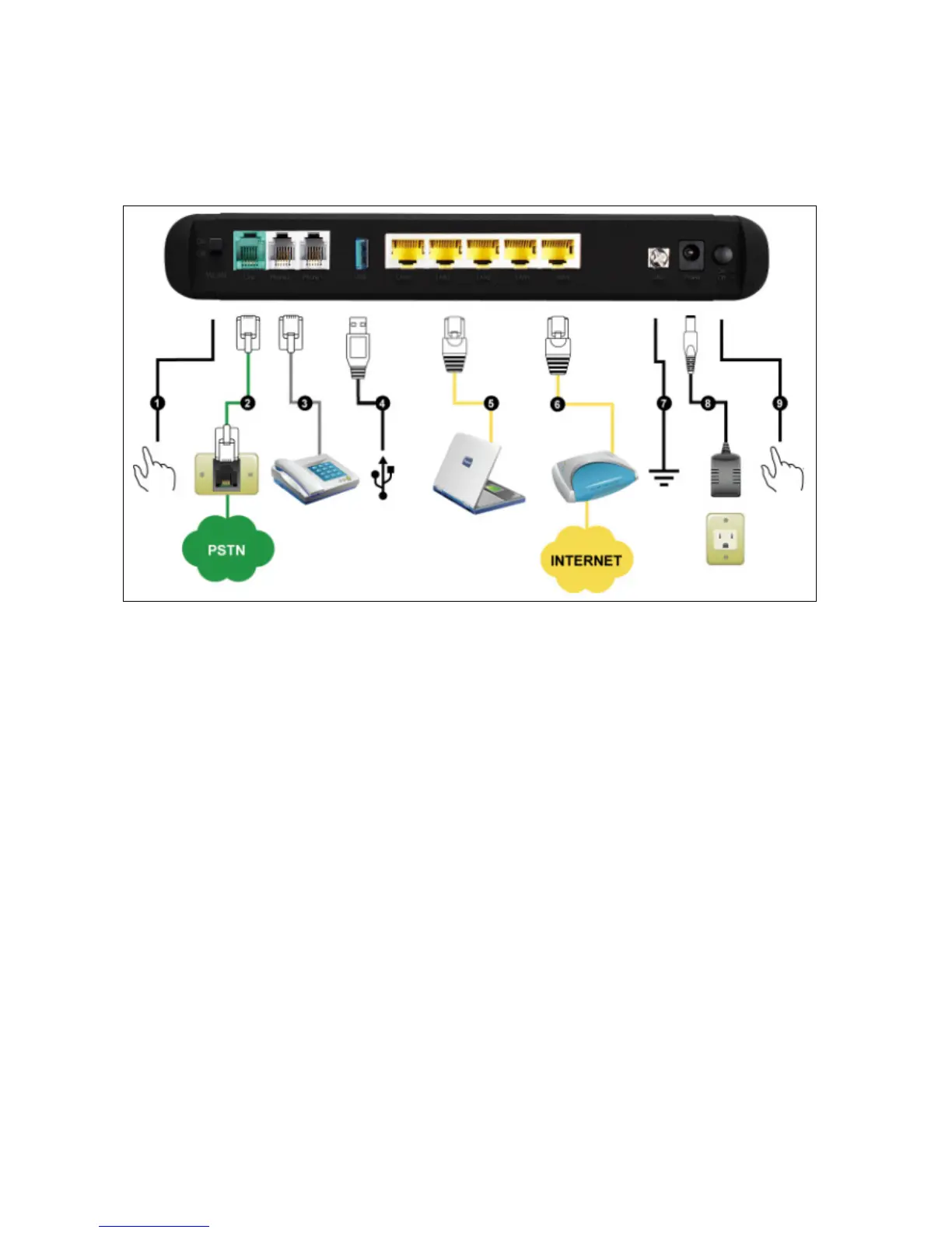
Rear Panel
1. WiFi Switch: Turn on/off wireless LAN.
2. Line: Connect to your original telephone line on the wall jack with RJ-11 cable.
3. Phone Port (1-2): Connect to your phones using standard phone cabling (RJ-11).
4. USB: Connect to a 3G USB dungle or a printer.
5. LAN: Connect to your Ethernet enabled computers using Ethernet cabling.
6. WAN: Connect to your broadband modem using an Ethernet cable.
7. Ground: A conducting connection with the earth. Connect with the ground so as to make the earth a part of
an electrical circuit using metal wire.
8. Power Receptor: Receptor for the provided power adapter.
9. Power Switch: Press down to turn-on DVG-N5412SP.
WARNING: DO NOT (1) connect the phone ports to each other (FXS to FXS) or (2) connect any
phone port directly to a PSTN line (FXS to PSTN) or to an internal PBX line (FXS to PBX extension).
(3) Stacking is forbidden. Doing so may damage your VoIP Router.