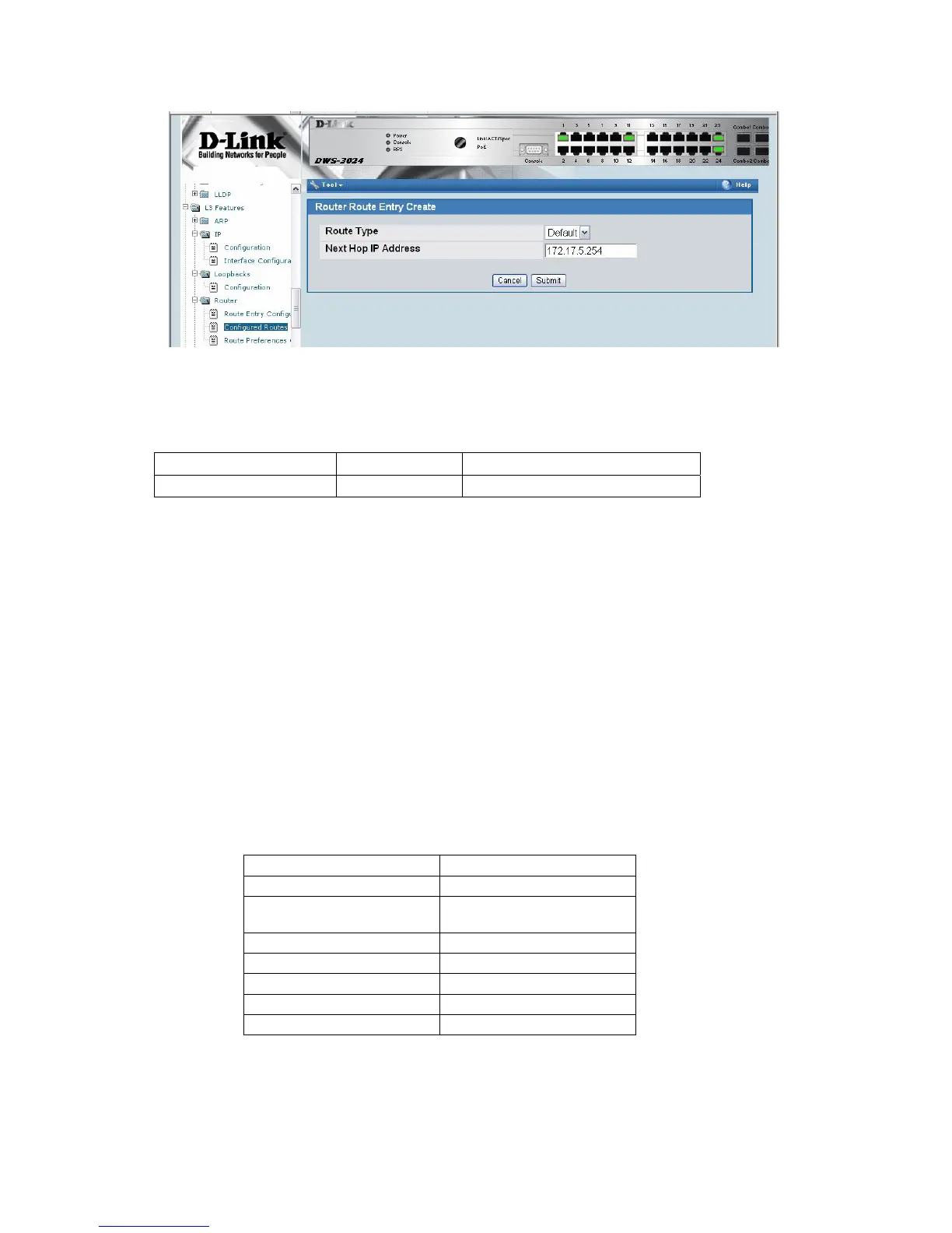
Proper static routes to Wireless Switch (WS1) must be also configured on the “customer”
L3 device as well. In a customer environment, you would need to configure the following
static routes on the customer’s L3 device.
Network Address Mask Next Hop IP Address
192.168.10.0 255.255.255.0 172.17.5.253
Note: The above static route provides an IP path back to the loopback interface on the
WS for the remote AP to access to become managed by the Unified Access System.
Without additional routes, wired clients on the customer’s L3 device will not be able to
reach other subnets on the WS. This includes connectivity between wireless clients on
AP1 and AP2 if they associate with a non-Tunneled SSID.
3.1.4 DHCP Server
You need to configure a new IP address pool for the clients that connect to the L3 Tunnel
network (the FTP/Audio/Video server and the wireless clients that connect to the L3 Tunnel
SSID). The DHCP server should already be enabled from Scenario 2.
6. From the LAN menu, click Administration Æ DHCP Server Æ Global Configuration
7. In the Admin Mode field, select Enable, then click Submit to enable the DHCP server..
8. Select Pool Configuration in the Navigation tree.
9. For the new address pool, select create and specify the following settings:
Pool Name
Tunnel
Type of Binding
Dynamic
Network Number
192.168.250.0
Network Mask
255.255.255.0
Days
1 day
Hours
0
Minutes
0
Default Router Address
192.168.250.254
10. Click Submit to create the address pool.

 Loading...