DGS-3610 Series H/W Installation Guide Chapter 2 Installation
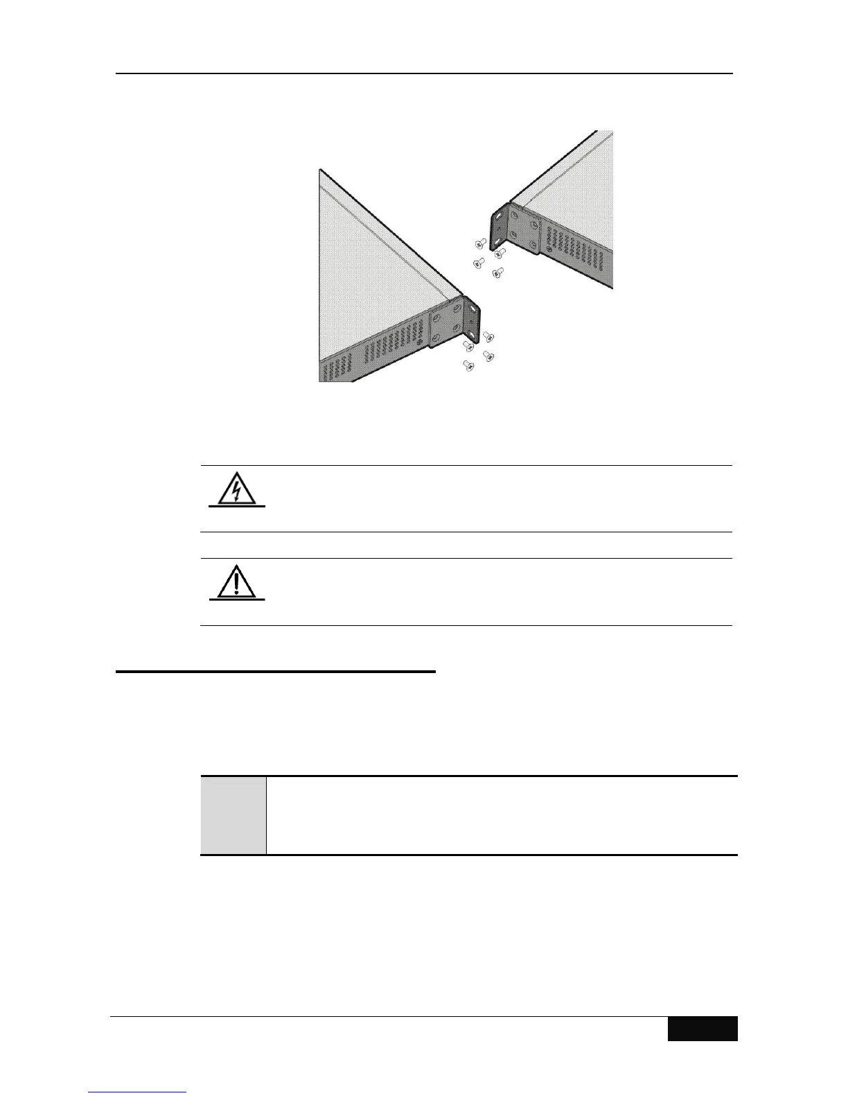
Figure 2-1 Schematic Diagram for Installing the Handle
The above figure shows the schematic diagram for installing the handle on the switch. There
are eight screw holes on the handle. Align the handle with the screw holes on the side wall of
the switch and tighten the sunk screws.
To prevent overheating of the switch, place the switch in a location where
the ambient temperature is no more than 40°C. Also the spacing of at least
10cm should be reserved around the chassis for good ventilation.
Do not place any heavy objects on the switch.
2.3 Rack Mounting
You can also mount the switch in the wiring section of a standard 19-inch rack. First fasten
the accessories for rack mounting from the carton onto both sides of the switch and then
mount the switch into the 19-inch rack with screws. When you are doing this, you can use
the attached two L-shaped handle fastening brackets and M3*10FMO sunk screws.
Keep the fastening brackets with handles closely onto both sides of the switch,
align with the screw holes and fasten them with M3*10FMO sunk screws, as
shown in the following diagram:

 Loading...