Chapter 2 Installation DGS-3610 Series H/W Installation Guide
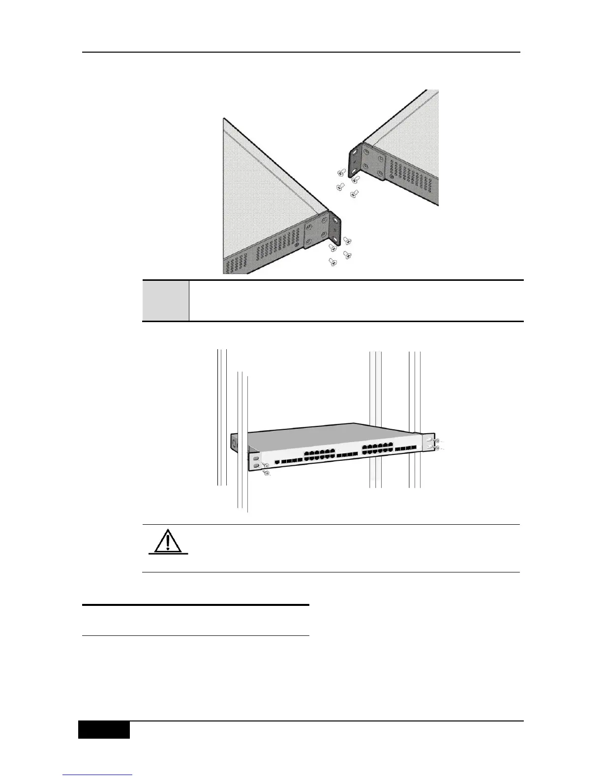
Figure 2-2 Schematic Diagram for Installing the L-Shaped Fastening Bracket
Fasten the switch onto the rack, as shown in the following diagram. You should
prepare the screws needed for rack mounting by yourself.
Figure 2-3 Schematic Diagram for Fastening the Switch
Please ensure that the ventilation holes and fans on both sides and at the
back of the chassis are not blocked.
2.4 System Connection
2.4.1 Connecting the RJ-45 Port
Use shielded or unshielded twisted pair cables with RJ-45 connectors on both ends. Use
cables of Category 3, 4, and 5 to connect the 10Mbps Ethernet, and use cables of Category
5 to connect the 100/1000Mbps Ethernet ports. Connect one end of a cable to the network
card or the RJ-45 port of another switch/HUB, and the other end to the RJ-45 port of the

 Loading...