Do you have a question about the DAC GDC31 and is the answer not in the manual?
Details the GDC31 Roll Steering Converter's design, features, and capabilities, including its inputs and outputs.
Visual representation of the GDC31 RSC system, showing its connections to GPS, Annunciator, and Autopilot.
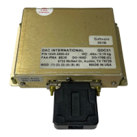
Lists the available part numbers for the GDC31 Data Converter, including different speed variants.
Outlines the software development, PMA approval, and environmental standards met by the GDC31.
Details the physical dimensions and weight of the GDC31 LRU and the optional Isolation Coupler.
Covers input voltage, input current, and annunciator lamp current requirements for the GDC31.
Specifies the format and baud rate options for serial data input from a GPS navigation system.
Describes the analog bank angle command output, including scale factors and phasing options.
Details the ARINC 429 digital output, including labels for bank angle command and ground speed.
Explains the AC/DC excitation inputs used to excite the heading bug on the HSI or DG.
Details the input specifications for the first reference voltage input (AP Ref 1).
Details the input specifications for the second reference voltage input (AP Ref 2).
Describes the normally open relay contact for controlling an external GPS mode annunciator.
Defines the valid voltage range for the GPS Super Flag input signal.
Lists the certification standards including PMA, DO-178B, and DO-160D for the GDC31.
Provides information on the Mean Time Between Failures (MTBF) for the GDC31 unit.
Explains how the GDC31 receives GPS data and computes bank angle commands for the autopilot.
Details the analog Roll Sum Steering (RSS) signal and its interaction with the autopilot.
Describes the function and voltage ranges of the two reference inputs for the GDC31.
Explains the ARINC 429 digital output labels (121 and 312) for autopilot integration.
How the GDC31 controls the GPS mode annunciator via a relay contact.
Details the function of the Super Flag input and its effect on GDC31 operation.
Lists essential installation items that are not included with the GDC31 kit.
Specifies the recommended crimp tools and positioners for reliable connector connections.
Guidance on mounting the GDC31 and optional Isolation Coupler in the aircraft structure.
Instructions and recommendations for fabricating wiring harnesses and ensuring continuity.
Procedure for determining the correct scale factor for autopilot integration.
Explanation of how program pins (J1-10, J1-22) are used to select RSS output levels.
Guidance on selecting the correct phase relationship for the steering signal.
How to configure the GDC31 for position-based or rate-based autopilots via program pins.
Procedure for selecting the appropriate baud rate for GPS data communication.
Instructions for configuring the GPS to output data in the required Aviation Format.
Step-by-step instructions for safely removing the GDC31 unit from the aircraft.
Step-by-step instructions for installing the GDC31 unit into the aircraft.
Procedure for removing the Mode Annunciator/Switch from its mounting.
Procedure for installing the Mode Annunciator/Switch.
Procedure for verifying GDC31 functionality through ground-based tests.
Procedure for verifying GDC31 functionality during flight operations.
Provides dimensional drawing for the GDC31 Roll Steering Converter unit.
Provides dimensional drawing for the Mode Annunciator/Switch (P10280).
Provides dimensional drawing for the optional Isolation Coupler assembly.
Details the ARINC 429 Label 121 format for bank angle command data.
Details the ARINC 429 Label 312 format for ground speed data.
General overview of interconnect diagrams for wiring the GDC31.
Wiring diagram for KI 525/525A with KA 52/KA 57 integration.
Wiring diagram for ARINC HSI with Century IV autopilot integration.
Wiring diagram for ARINC HSI with S-TEC 50, 55 or 60 autopilot integration.
Wiring diagram for NSD 360A/1000 with Century IV autopilot integration.
Wiring diagram for NSD 360A/1000 with S-TEC 50 or 55 autopilot integration.
Wiring diagram for ARINC HSI with Century II or III autopilot integration.
Wiring diagram for KI 525A with KFC 150 autopilot integration.
Wiring diagram for NSD 360 with ARC 400B (10VAC) integration.
Wiring diagram for 52D54 DG with STEC 50, 55 or 60 autopilot integration.
Wiring diagram for NSD 360 with ARC 400B (DC) integration.
Wiring diagram for NSD 360 with Century 2000 autopilot integration.
Wiring diagram for NSD 360A with Century II or III autopilot integration.
Wiring diagram for HSI-70C with ARC 1000 integration.
Wiring diagram for KI 525A with KFC 200 / 300 autopilot integration.
| Model | GDC31 |
|---|---|
| Category | Media Converter |
| Distance | 20 Km |
| Fiber Type | Single Mode |
| Power Supply | 5V DC |