Equipment Installation Manual,
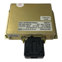
GDC31 Roll Steering Converter
NOTE:
Perform the following setup procedures in this section if a wiring diagram for a particular autopilot is not
included in this manual.
Steering Output Scale Factor Determination
The GDC31 is designed to mimic the heading error signal produced by the existing HSI or DG, so it can
operate with the wide variety of autopilots in current use. These various autopilots employ a wide range
of reference voltages and scale factors to interface with the array of HSI and DG control heads.
Reference voltage, or excitation, is the autopilot signal used to excite the Heading Select bug in the HSI or
CDI. As used in this manual, scale factor refers to the autopilot’s response to the heading error input
signal, expressed in volts per degree of bank. Examples are 200mv/deg and 60mv/deg. Examples of
excitation voltage are 26Vac and 15Vdc. The GDC31 firsts computes the bank angle using data from the
GPS. It then uses the reference voltage along with the scale factor setting (gain setting) to produce a
signal that feeds into the autopilot’s heading error input to produce the desired bank angle.
The GDC31 has eight (8) choices for scale factor, selected with a combination of program pins (2 each)
and reference inputs (2 each). Tables 1 and 2 describe the program pin combinations for the various scale
factors. To determine the appropriate setting for a given autopilot, first determine the autopilot excitation
amplitude in volts (AC or DC). Next, determine the autopilot scale factor from the autopilot maintenance
data. The scale factor needs to be expressed as volts/degree of bank. Divide the scale factor by the
excitation (scale factor / excitation voltage). Then look in Tables 1 and 2 for the nearest Scaling value to
the one just computed.
If the gain is set too high, the commanded course intercept will be overly aggressive. For 90-degree
course changes, too much gain will often cause the aircraft to turn inside the new course then S-turn back
to capture the track.
If the gain is set too low, the commanded course intercept will be sluggish. For a 90-degree course
change, too little gain will often cause the aircraft to overshoot the desired course then S-turn back to
capture the track. Some autopilots limit the maximum bank angle to less than the 30 degrees, 22 degrees
for example. In these cases, the aircraft will exhibit the symptoms of too little gain because the aircraft
cannot turn sharp enough to capture the track without overshooting. Examine the attitude indicator during
a 90-degree course change to verify that the aircraft banks to 30 degrees, or in the case of rate based
autopilots, to a standard rate turn.
1049-2510-01 G.doc
1049-2510-01
Rev G Page 16 of 47