Equipment Installation Manual,
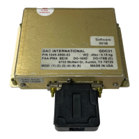
GDC31 Roll Steering Converter
OPERATION:
Overview
The GDC31 Roll Steering Converter receives RS232 or RS422 serial data in RNAV 0, RNAV 1, King 0
or King 1 format from a GPS navigation system. It extracts Cross Track, Ground Speed and Track Angle
Error information from the data stream to compute an appropriate bank angle command to return the
aircraft to the Desired Track computed by the GPS navigation system.
Analog Output
The GDC31 produces an analog Roll Sum Steering (RSS) signal that drives the heading channel of the
autopilot. Phasing and amplitude of the RSS signal is based on the reference input supplied to the GDC31
from the autopilot and the gain and phase settings established by the program pins (refer to Tables 1, 2
and 3). The GDC31 will accept either an AC or a DC reference input as well as reference inputs that
contain an offset from airframe ground. The internal circuitry implements a multiplying Digital-to-
Analog converter that uses the external reference input to produce the desired signal output amplitude and
phase relative to the reference input. Certain installations (Century II and III, for example) will not accept
a heading error signal referenced to ground, so require the Isolation Coupler in order to transformer
isolate the GDC31 output signal.
Reference Inputs (Excitation)
The GDC31 contains two reference inputs to accommodate the wide range of reference voltages
available. Input Ref1 will accommodate excitation voltages up to a maximum input of 42 volts peak
(30Vrms). Input Ref2 will accommodate excitation voltages up to a maximum of 15 volts peak (15Vdc
or 10.6Vrms). The determination of which reference to use will depend on the gain needed to match the
autopilot scale factor as well as the maximum expected reference voltage. Certain installations (Century
II and III, for example) produce a reference voltage that is floating relative to airframe ground. These
installation require the Isolation Coupler in order to transformer isolate the GDC31 reference input signal.
ARINC 429 Output
The GDC31 produces an ARINC 429 digital output containing labels 121 and 312 intended to drive
digital autopilots or digital autopilot converters.
429 Label Output
(Octal) Description Rate
121 Bank Angle Command (BNR) 20 Hz
312 Ground Speed (BNR) 20 Hz
1049-2510-01 G.doc
1049-2510-01
Rev G Page 12 of 47