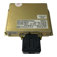
Equipment Installation Manual,
GDC31 Roll Steering Converter
AP Offset Input:
Autopilot Offset.................................For autopilots that use a signal common that is not airframe
ground. Many use 5Vdc (relative to airframe) as the heading
bug signal common. In these cases, connect the autopilot signal
common to the GDC31 offset input pin, P1-19.
Maximum Input Level ..................7 volts peak (5Vrms)
Load: ............................................10K
Annunciator Output:
GPS Coupled......................................Normally Open relay contacts configured as a SPST switch
intended to control an external GPS mode annunciator. The
GDC31 closes the contacts when the steering output is valid. It
cycles the contacts between open and closed at a 1 Hz rate if
steering data is invalid. Closed contacts connect pins P1-24 and
P1-12.
Max current:.......................................250mA
Flag Input:
Description.........................................Valid input to the GDC31 at J1-25, supplied from a GPS
receiver Super Flag output (14 or 28V).
Voltage:..............................................Greater than 6V is valid, less than 3V is invalid.
Load ...................................................200K ohms
Certification:
PMA
DO-178B............................................Level C
DO-160D............................................D1/BADSXXXXXXABBBAVB/A3E3/XXX
Reliability:
MTBF.................................................Greater than 50,000 hours.
1049-2510-01 G.doc
1049-2510-01
Rev G Page 11 of 47