D1146/D1146TI/DE08TIS
MAINTENANCE MANUAL
80
Printed in Jan. 2001 PS-MMA0415-E1A
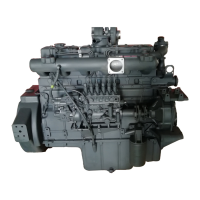
z Idler gear pin with oil hole is assembled
toward cylinder block.
z Install the idle gear by coinciding the
marks impressed on the crank gear, cam
gear, fuel injection pump drive gear, and
idle gear.
z Install a thrust washer on the idle gear
and tighten to specified torque.
Torque 3.1 kg.m
z Check and adjust the amount of backlash
between gears using a feeler gauge.
Measuring position
(between)
Backlash Limit
cam gear & idle gear
0.16 ∼ 0.28 mm
0.35 mm
crank gear & idle gear
0.16 ∼ 0.28 mm
0.35 mm
injection pump & idle gear
0.16 ∼ 0.28 mm
0.35 mm
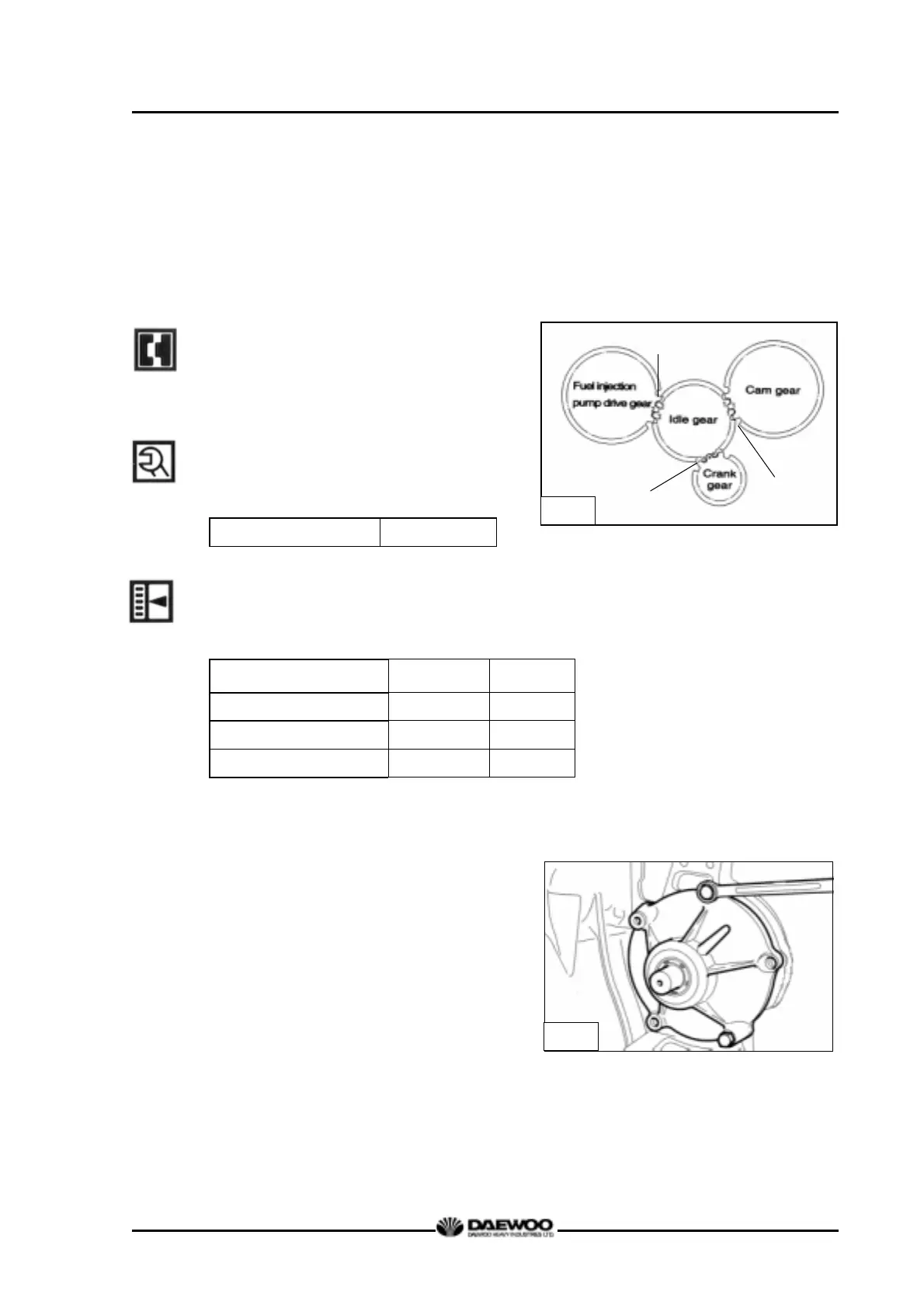
3.3.15. Injection pump flange
z After assembling the fuel injection pump
gear to the idle gear, tighten the
assembling bolts of the injection pump
flange.
z Mount gasket by aligning the bolt holes
with the pin holes on the bearing
housing.
z Turning the flywheel, adjust the pointer
to the position of the engraved scale.
z After adjusting the injection timing of fuel
injection pump drive gear, tighten the
G1097
G1054
Mark “2”
Mark “1”
Mark “o”