4-70 Inspection, Maintenance and Adjustment K1000896E Operation and Maintenance Manual
2. Release the screw cap (6, Figure 114 and
Figure 116) and unscrew.
3. Release the lock nut (5, Figure 114) and
turn the adjusting screw (4)
counterclockwise until the brake disk is
free.
4. Install lock nut (5, Figure 114) and screw
cap (6) and tighten both as far as possible.
This will protect the parking brake
assembly from dirt.
NOTE: Now, the vehicle does not have
any brake function. The vehicle
must be secured against
moving away with proper
means. Before putting the
vehicle into operation again, the
brake has to be adjusted
according to adjusting
regulations.
ADJUSTING REGULATIONS
During this adjusting process, the parking brake must be released, i.e. the bank of cup springs (3, Figure
114) must be completely pretensioned.
1. Park vehicle on an even surface and place wheel chocks in front of and behind tires. Only then,
release the parking brake.
2. Release the screw cap (6, Figure 114) and unscrew.
3. Release the lock nut (5, Figure 114) (size 24 or 30) and turn the adjusting screw (4) with socket
wrench (size 8 or 10) clockwise until the two brake pads (1 and 2) make contact with the brake disk.
4. Turn the adjusting screw (4, Figure 114) counterclockwise and set the clearance specified in the
following table.
Type Adjusting Screw Clearance (mm) Turns
Small M 16 (size 8)
min.
0.5 mm
(0.02 in)
1/4
Rated clearance
1.0 mm
(0.04 in)
1/2
max
1.5 mm
(0.06 in)
3/4
Large M 20 (size 10)
min.
1.0 mm
(0.04 in)
2/5
Rated clearance
2.0 mm
(0.08 in)
4/5
max
3.0 mm
(0.12 in)
1 1/5
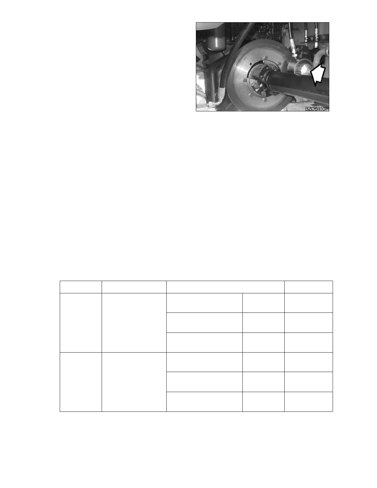
Figure 116