User's Manual
22
Icon Port Name Function
1–8
Alarm input port
1–8
●
There are two groups. The first group is from
port 1 to port 4; the second group is from port 5
to port 8. They are to receive the signal from the
external alarm source. There are two types; NO
(normal open)/NC (normal close).
●
When your alarm input device is using external
power, please make sure the device and the NVR
have the same ground.
GND Alarm input ground port.
NO1–NO3
Alarm output port
1–3
●
3 groups of alarm output ports. (Group 1: port
NO1–C1; Group 2: port NO2–C2; Group 3: port
NO3–C3). Output alarm signal to the alarm
device. Please make sure there is power to the
external alarm device.
●
NO: Normal open alarm output port.
●
C: Alarm output public end.
C1–C3
A
RS-485
communication
port
RS485_A port. It is the cable A. You can connect to
the control devices such as speed dome PTZ.
B
RS485_B. It is the cable B. You can connect to the
control devices such as speed dome PTZ.
Power input port Input DC 12V/4A.
Power switch — Power on/off button.
PoE PORTS —
Built-in Switch. Support PoE or ePoE function.
●
For ePoE series product, port 1 to port 8 are the
ePoE ports. ePoE port supports 300
meters@100Mbps, 800 meters@10Mbps. Port 9
to port 16 are general PoE ports.
●
The 8 PoE series product supports total 130W.
●
The 16 PoE series product supports total 130W.
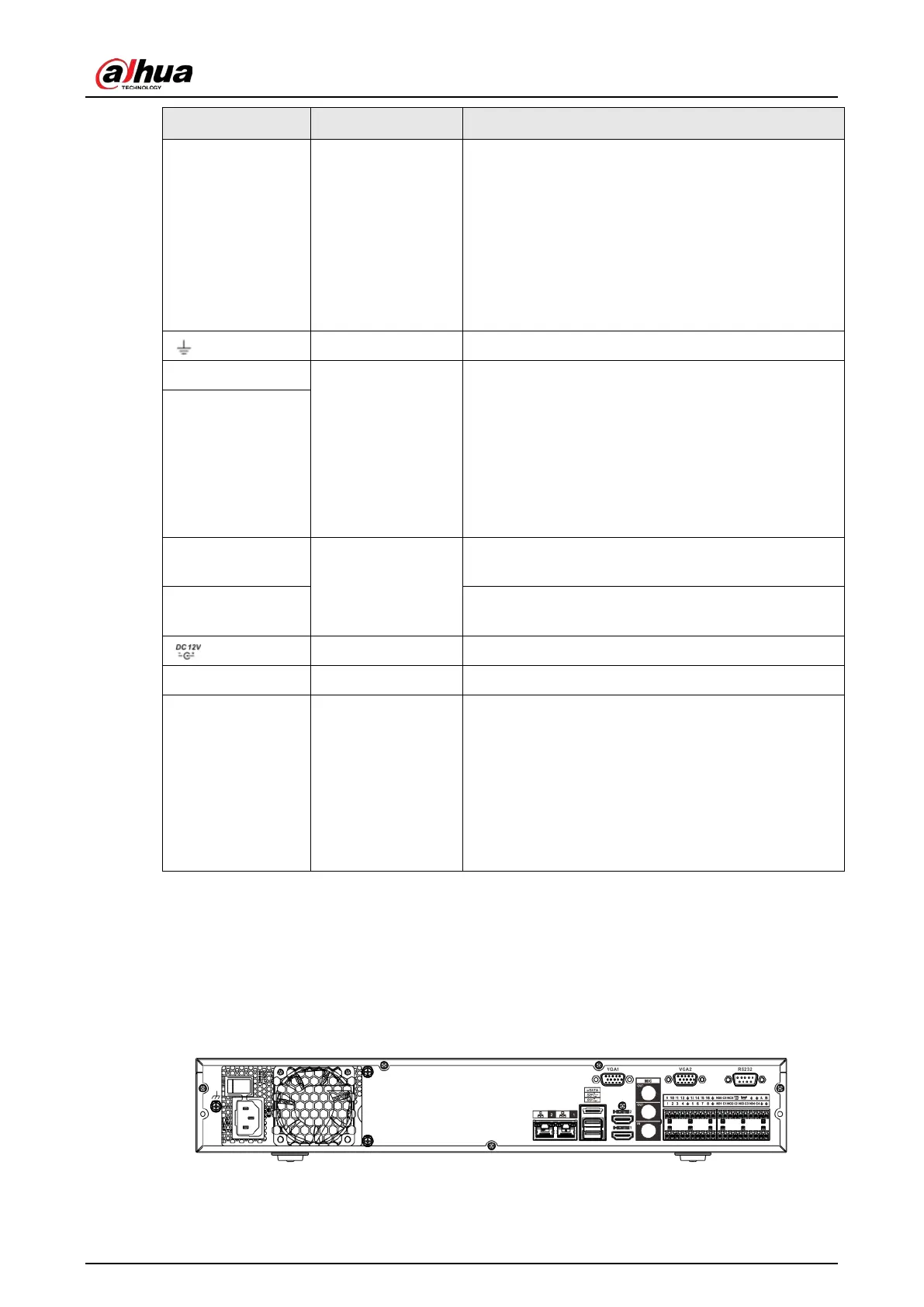
2.2.5 NVR54-4KS2/NVR58-4KS2/NVR54-16P-4KS2/NVR58-16P-
4KS2/NVR54-24P-4KS2/NVR58-16P-4KS2E Series
The NVR54-4KS2/NVR58-4KS2 series rear panel is shown as below.
Figure 2-38 Rear panel
The NVR54-16P-4KS2/NVR58-16P-4KS2 series rear panel is shown as below.

 Loading...