6 Electrical installation
Installation manual
27
EBLA09~16D + EDLA09~16D
Daikin Altherma 3 M
4P620239-1B – 2022.05
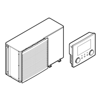
K1M K2MK2M
1 3 5 13
2 4 6 14
K5M
1 3 5 13
2 4 6 14
1 3 5 13
2 4 6 14
Ω
Ω
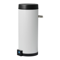
To connect the backup heater kit to the outdoor unit
The wiring between the backup heater kit and the outdoor unit is as
follows:
1 2 3 4 5
6 7 8 9 10
X3M
X15M
1 2
1 2
X5M
X15M
EKLBUHCB6W
A
B
HV LV
A Outdoor unit
B Backup heater kit
HV High voltage connections (backup heater thermal
protector + backup heater connection)
LV Low voltage connection (backup heater thermistor)
NOTICE
The distance between the high voltage and low voltage
cables should be at least 50mm.
1 On the backup heater kit, connect the LV and HV cables to the
appropriate terminals as shown in the illustration below.
2 On the outdoor unit, connect the HV cable to the appropriate
terminals as shown in the illustration below.
6 7 8 9 10
X15M
X3M.1
X3M.2
X3M.3
X3M.4
X3M.5
EKLBUHCB6W
HV
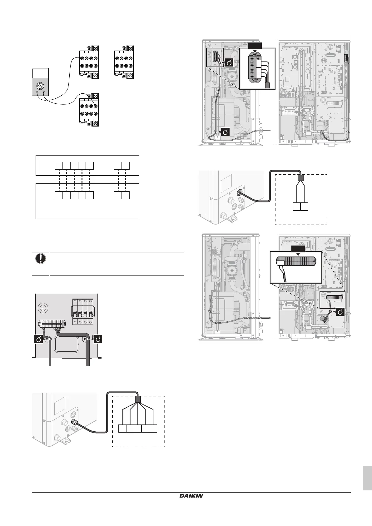
3 On the outdoor unit, connect the LV cable to the appropriate
terminals as shown in the illustration below.
1 2
X15M
X5M.1
X5M.2
EKLBUHCB6W
LV
4 Fix the cables with cable ties to the cable tie mountings.
Bypass valve kit necessity
For reversible systems (heating+cooling) in which an external
backup heater kit is installed, the installation of valve kit EKMBHBP1
is required if condensation is expected inside the backup heater.