174
FTX-N/U, FVXS-N, FDMQ-R Series EDUS091558E
3P379970-10C
9
Wiring
WARNING
• Donotusetappedwires,extensioncords,orstarburstconnections,astheymaycauseoverheating,electricshock,orre.
• Do not use locally purchased electrical parts inside the product. (Do not branch the power for the drain pump, etc., from the
terminalblock.)Doingsomaycauseelectricshockorre.
• Be sure to install a ground fault circuit interrupter. (One that can handle higher harmonics.)
(This unit uses an inverter. Therefore, a ground fault circuit interrupter capable of handling higher harmonics must be used in
order to prevent the ground fault circuit interrupter malfunctioning.)
• Use an all-pole disconnection type circuit breaker with at least 1/8 inch (3mm) between the contact point gaps.
• When carrying out wiring, take care not to pull at the conduit.
• Donotconnectthepowerwiretotheindoorunit.Doingsomaycauseelectricshockorre.
• Do not turn on the circuit breaker until all work is completed.
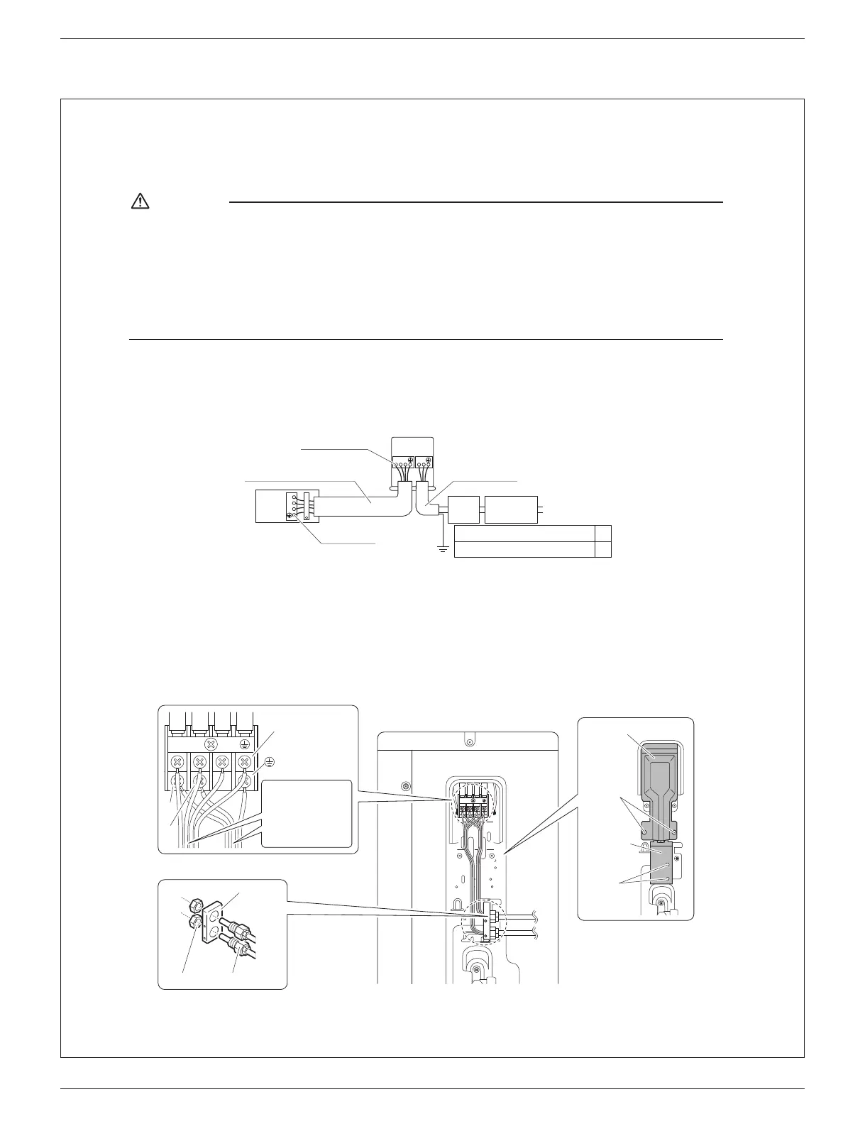
1) Strip the insulation from the wire (3/4 inch (20mm)).
2) Connect the inter-unit wires between the indoor and outdoor units so that the terminal numbers match. Tighten the
terminalscrewssecurely.Itisrecommendedthataatheadscrewdriverbeusedtotightenthescrews.
The screws are packed with the terminal block.
1
2
3
123
Circuit
breaker
Ground fault
circuit interrupter
Ground
Firmlyxthewireswith
theterminalscrews.
UseAWG16iftheconnectionwire
lengthislessthan33ft(10m),or
AWG14ifitis33ft(10m)ormore.
Outdoor unit
Indoor
unit
Powersupply
60Hz208-230V
Firmlyxthe
wireswiththe
terminalscrews.
UseAWG14wires.
RX09/12∗,RK09/12∗
RXN09/12/18∗,RKN09/12/18∗,RXL09/12/15∗
RX18/24∗,RK18/24∗
RXN24∗,RKN24∗
15A
20A
L
1
L
2
09/12 class
[Method of mounting conduit]
•Aprotectionplateisxedforprotectionfromthehigh-voltagesection.
1) Dismount the stop valve cover by removing the screw.
2) Dismount the protection plate by removing the 2 screws.
3) Dismount the conduit mounting cover by removing the 2 screws.
4) Pass wires through the conduit and secure them with a lock nut.
5) After completing the work, reattach the stop valve cover, the conduit mounting cover, and the protection plate to its
original position.
1
2
3
1
2
3
1
2
3
Screws
Conduit
mounting
cover
Screws
Protection plate
Power supply
terminal block
Shape wires so
that the protection
plate and conduit
mountingplatet
securely.
Conduit
Lock nut
Conduit
mounting
plate
L
1
L
2
01_EN_3P379970-10C.indd 9 10/18/2019 9:18:01 AM