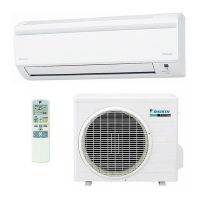
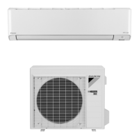
96
FTX-N/U, FVXS-N, FDMQ-R Series EDUS091558E
C: 3P379970-7B
4
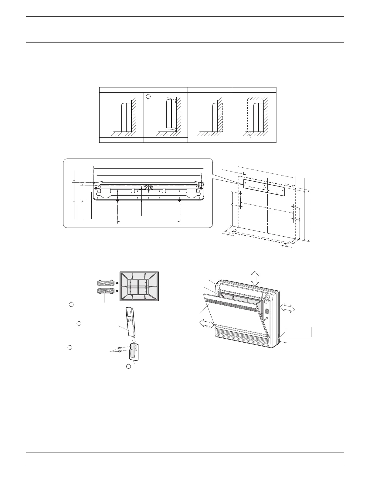
Indoor Unit Installation Diagram
• The indoor unit may be mounted in any of the 3 styles shown here.
Exposed Half concealed
Floor Installation Wall Installation
Concealed
Grid (field supply)
Mounting
plate
A
Molding
• Recommended mounting plate retention spots and dimensions.
unit: inch (mm)
(27-9/16 (700))
2-1/2 (64)
5-1/4
(134)
1 (26)
(23-5/8 (600))
22-5/8 (574)
5-1/2 (140)
9-13/16
(250)
5-7/8
(150)
9-1/16 (230)
25-3/8 (644)
8-1/4
(210)
6-5/16
(160)
1-3/8 (35)
1-3/8 (35)
1-3/8 (35)
18-11/16 (475)
19-11/16 (500)
3/8 (10)
2-9/16 (65)
3-1/8 (80)
11 (280)
1-7/8 (47)
Titanium apatite deodorizing
filter (2)
B
Front grille
Air filter
Front panel
1-15/16” (50mm)
or more from walls
2-3/4” (70mm) or more
1-15/16” (50mm)
or more from walls
Caulk pipe hole
gap with putty.
Fixing screw for
remote controller holder
1/8” × 13/16” (M3 × 20mm)
Remote controller holder
E
F
G
Wireless remote controller
01_EN_3P379970-7B.indd 4 11/12/2015 13:29:40