Installation manual
7
LRYEQ16A7Y1
CONVENI-PACK
4P448939-1A – 2016.07
6-1 Selection of Piping Material and Size
•
Make sure that the inner side and outer side of the piping used is clean and free of contaminants, such as sulphur, oxide, dust, chips, oil and fat, and water.
It is desirable that the maximum oil adhesion in the piping is 30 mg per 10 m.
• Use the following type of refrigerant piping.
Material: Seamless phosphorus deoxidized copper tube (C1220T-O for a maximum outer diameter of 15.9 mm and C1220T-1/2H for a minimum
outer diameter of 19.1 mm)
Refrigerant piping size and wall thickness: Decide the size and thickness from the following table.
(This product uses R410A. The withstand pressure of O type may be insufficient if it is used for piping with a minimum diameter of
19.1 mm. Therefore, be sure to use 1/2 H type with a minimum thickness of 1.0 mm.
If O type is used for piping with a minimum diameter of 19.1 mm, a minimum thickness of 1.2 mm will be required. In that case, be sure
to perform the blazing of each joint.)
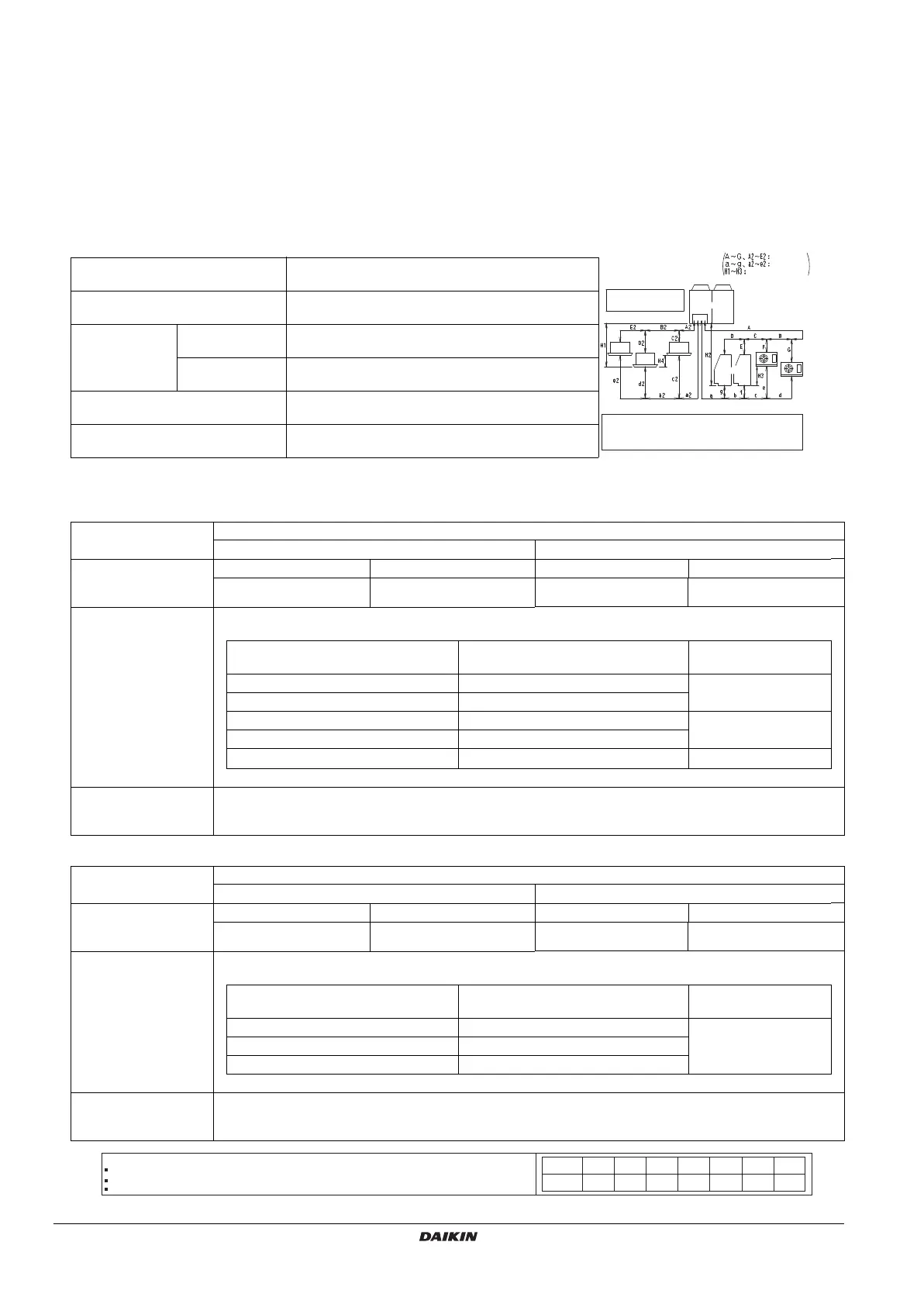
• Be sure to perform piping work within the range specified in the following table.
Refrigerant piping length
Max. permissible one-way piping
length (equivalent length)
a + b + c + d1 ≤130 m (d1 is d or e whichever is longer)
a2 + b2 + e1 ≤130 m (e1 is d2 or e2 whichever is longer)
Max. branch piping length (actual
length)
Refrigeration side: b + c + d1 ≤50 m (d1 is d or e whichever is longer)
Air conditioning side: b2 + e1 ≤30 m (e1 is d2 or e2 whichever is longer)
Max. difference in
height between
indoor and
outdoor units
unit below outdoor
unit
H1, H2 ≤35 m (Note)
unit above outdoor
unit
H1, H2 ≤10 m
Difference in height between unit
cooler and showcase
H3 ≤ 5 m
Difference in height between
air-conditioner indoor units
H4 ≤ 0.5 m
Note: A trap is required at 5 m intervals from outdoor unit.
In case of no connection
with booster unit
Outdoor unit
Showcase
Unit
cooler
Air
conditioner
Liquid piping
Gas piping
Difference in height
Note
When connecting the booster unit, refer to the
installation manual provided for the booster unit.
Refrigerant piping size
(Refrigeration)
Outdoor unit side Piping size (mm)
Liquid pipe Gas pipe
Piping between outdoor
unit and first branch
(A, a)
50 m or less 50~130 m 50 m or less 50~130 m
Ø9.5 × 0.8 (O type) Ø12.7 × 0.8 (O type)
Ø28.6 × 1.2 (1/2H type or H type) Ø28.6 × 1.2 (1/2H type or H type)
Piping between
branching areas
(B, b, C, c)
Select the piping from the following table in accordance with the total capacity of indoor units connected
downstream
Total capacity of indoor units after
branching
Gas pipe size Liquid pipe size
x <1.0 kW Ø9.5
× 0.8 (O type)
Ø6.4 x 0.8 (O type)
1.0 kW≤x<6.0 kW Ø12.7
× 0.8 (O type)
6.0 kW≤x<9.9 kW Ø15.9
× 1.0 (1/2H type or H type)
Ø9.5 x 0.8 (O type)
9.9 kW≤x<14.5 kW Ø19.1
× 1.0 (1/2H type or H type)
x≥14.5 kW Ø22.2
× 1.0 (1/2H type or H type)
Ø12.7 x 0.8 (O type)
No size after branching can exceed the size of any upstream piping.
Piping between
branching areas and
each unit
If the size of the connection pipe of the indoor unit exceeds that of the branch pipe shown in the table above,
enlarge the size of the connection pipe near the indoor unit before connecting it.
(Air-Condition)
Outdoor unit side Piping size (mm)
Liquid pipe Gas pipe
Piping between outdoor
unit and first branch
(A2, a2)
50 m or less 50~130 m 50 m or less 50~130 m
Ø9.5 × 0.8 (O type) Ø12.7 × 0.8 (O type)
Ø28.6 × 1.2 (1/2H type or H type) Ø28.6 × 1.2 (1/2H type or H type)
Piping between
branching areas
(B2, b2)
Select the piping from the following table in accordance with the total capacity of indoor units connected
downstream
Total capacity of indoor units after
branching
Gas pipe size Liquid pipe size
x<150 Ø15.9
× 1.0 (1/2H type or H type)
Ø9.5 x 0.8 (O type)
150≤x<200 Ø19.1
× 1.0 (1/2H type or H type)
200≤x≤300 Ø22.2
× 1.0 (1/2H type or H type)
No size after branching can exceed the size of any upstream piping.
Piping between
branching areas and
each unit
If the size of the connection pipe of the indoor unit exceeds that of the branch pipe shown in the table above,
enlarge the size of the connection pipe near the indoor unit before connecting it.
*
In case the required pipe sizes (inch sizes) are NOT available, it is also allowed to use other diameters (mm sizes), taken the following into account:
Select the pipe size nearest to the required size. See the table on the right.
Use the suitable adapters for the change-over from inch to mm pipes (field supply).
The additional refrigerant calculation has to be adjusted as mentioned in "Method of calculating “additional refrigerant charging quantity”
Note:
6.4 mm
28 mm
6 mm 10 mm 12 mm 16 mm 18 mm 22 mm
Metric
Inch
28.6 mm9.5 mm 12.7 mm 15.9 mm 18.1 mm 22.2 mm
4PEN448939-1A.book Page 7 Monday, September 5, 2016 7:12 PM
 Loading...