Installation manual
19
LRYEQ16A7Y1
CONVENI-PACK
4P448939-1A – 2016.07
*1 The cylinder’s internal pressure will drop when there is little refrig-
erant remaining in the cylinder, making it impossible to charge the
unit, even if the liquid shutoff valve opening is adjusted. In this sit-
uation, replace the cylinder with one that has more refrigerant
remaining.
Additionally, if the piping length is long, replenishing while the liquid
shutoff valve is fully closed may lead to activation of the protection
system, causing the unit to stop operation.
1. After the work is completed, apply a screw lock agent (for flare
nuts) to the screws of the shutoff valves and service ports.
Refer to the "Handling Precautions for Valve Cover" and "Handling
Precautions for Service Port" in "6-6 Connecting the Refrigerant
Piping" for the handling of the valve covers and service ports.
2. After the refrigerant replenishment is completed, fill out the item
"total amount of refrigerant replenishment". Refer to page 18 of this
manual.
[Precautions for refrigerant cylinder]
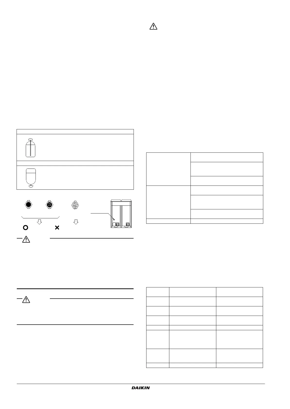
At the time of refrigerant filling, check whether the siphon tube is pro-
vided. Then locate the cylinder so that the refrigerant will be filled in
the state of liquid (see table below).
R410A is a mixed refrigerant, the composition of which may change
and the normal operation of the system may not be possible if the
refrigerant is filled in the state of gas.
[Check through sight glass]
• Fully open the shutoff valves on the liquid and gas sides after
the refrigerant replenishment is finished.
The compressor will malfunction if the system is operated with the
shutoff valves closed.
• Apply a screw lock agent to the screws of the valve cover
mounting parts and service ports.
(Otherwise, dew condensation water will intrude and freeze inside
and cause cap deformation or damage, which may result in refrig-
erant gas leakage or compressor malfunctions.)
When the refrigerant charging procedure is done or when pausing,
close the valve of the refrigerant tank immediately, remaining pressure
might charge additional refrigerant. Possible concequence: Incor-
rect refrigerant amount.
12. TEST RUN
For test run operators
Do not operate the outdoor unit alone on a trial basis.
When you connect a booster unit, refer to the installation manual
attached to the booster unit before a test run.
Test run procedure
Use the following procedure to perform a test run after installation
work is complete for the entire system:
1. Fully open the shutoff valves on the gas and liquid side of the out-
door unit.
2. Check that the electric accessory box lids of the outdoor unit, the
indoor unit (air-conditioner, refrigeration showcase, refrigeration
unit cooler) and the piping cover of the outdoor unit are closed.
Then turn on the outdoor and indoor units (air conditioner, refriger-
ation showcase, refrigeration unit cooler).
3. Turn on the operation switch from the inspection door of the out-
door unit. (The outdoor fan rotates in about 10 minutes after the
operation switch is turned on and the compressor starts.)
4. Push the ON/OFF button on the remote controller of the outdoor
unit (air-conditioner) to operate the unit.
5. Check the sealing condition through the sight glass of the outdoor
unit. In case of shortage of refrigerant, check if the refrigerant is
charged to the specified level.
6. Check the following on each unit.
7. Be sure to turn off the operation switch before turning off the power.
Error diagnosis
• Check the following if nothing is displayed on the remote controller
during the test run.
<Indoor unit (air-conditioner)>
1. Is the power turned on?
2. Is the wire broken or incorrectly wired (between the power, the
indoor unit and the remote controller)?
3. Has the fuse on PCB melted?
• Take the following action if you find a malfunction code on the
remote controller during the test run.
Cylinder provided with siphon tube.
Other cylinders
Stand the cylinder upright and fill the refrigerant.
(There is a siphon tube inside, which makes it
possible to replenish the refrigerant in the state of
liquid without setting the cylinder upside down.)
Stand the cylinder upside down and fill the
refrigerant.
(Pay attention so that the cylinder will not topple
down.)
Full of liquid
A little foam
flows.
Sealing state
Foam always
comes out.
Refrigerant insufficiency
Sight glass
Refrigeration showcase
Cold air should be blowing and the tempera-
ture should decrease to the preset level.
The electronic expansion valve should be
controlled on an appropriate superheated
degree.
The unit should start defrosting operation by
the time set on the timer.
Refrigeration unit cooler
Cold air should be blowing and the tempera-
ture should decrease to the preset level.
The electronic expansion valve should be
controlled on an appropriate superheated
degree.
The unit should start defrosting operation by
the time set on the timer.
Air-conditioner Cold air (or hot air) should be blowing.
Malfunction
code
Defect at installation Action to be taken
E3, E4 Shutoff valves closed
Fully open the shutoff
valves.
L4 The air passage is blocked.
Remove obstacles blocking
the air passage.
U1
Reverse-phase of the power
supply
Exchange two wires out of
three power supply wires.
U2 Voltage drop Check the voltage drop.
U4, UF
Wrong wiring of transmis-
sion lines between units
Check the connection of
transmission lines between
the outdoor unit and the air
conditioner.
UA
In the case of system dis-
crepancy
Check if the air conditioner is
connected as should be
assembled.
E2 Electric leak See *1.
4PEN448939-1A.book Page 19 Monday, September 5, 2016 7:12 PM
 Loading...