LRYEQ16A7Y1
CONVENI-PACK
4P448939-1A – 2016.07
Installation manual
14
When closing the unit the electrical component box cover, make sure
that the sealing material on the lower back side of the cover is not
caught and bend towards the inside.
1 Electrical component box cover
2 Front side
3 Power supply terminal block
4 Sealing material
5 Moisture and dirt could enter
X Not allowed
O Allowed
8-3 Procedure for Incoming Wiring
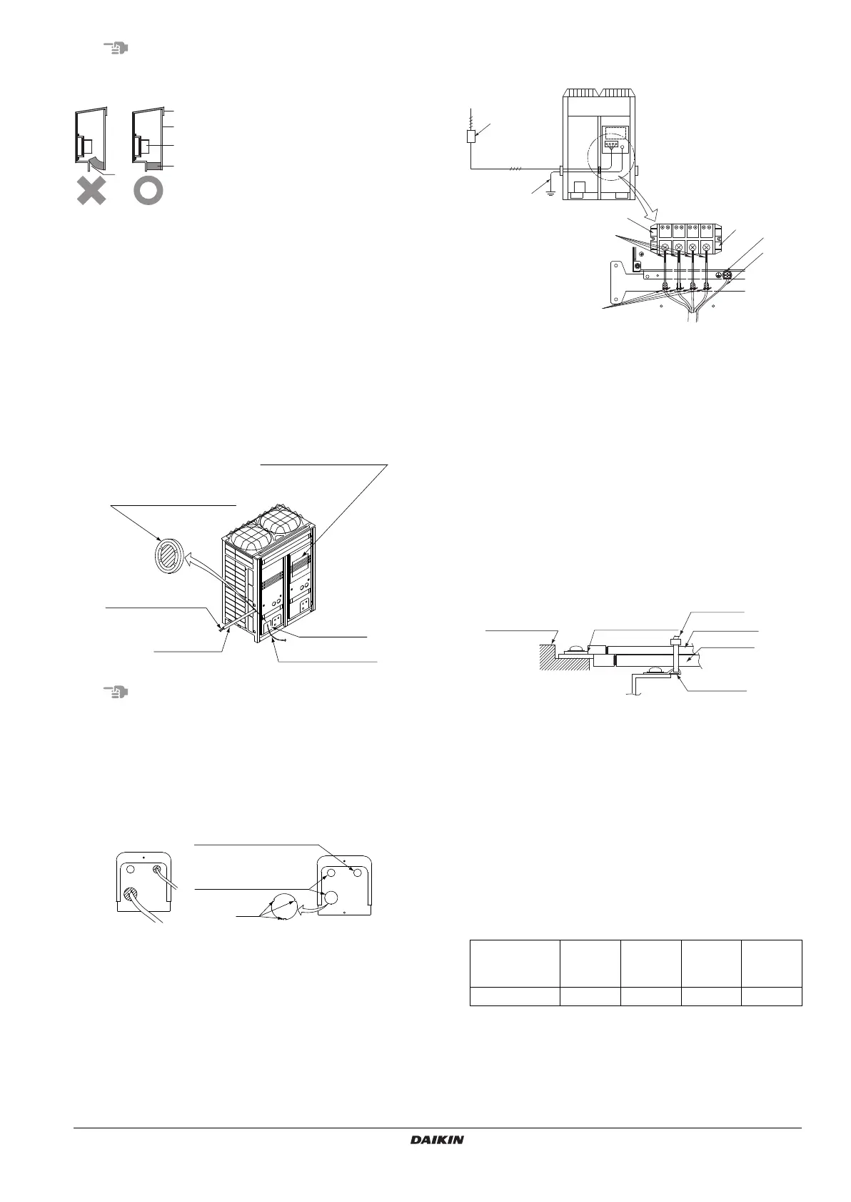
• Route high-voltage wiring (power supply wiring, earth wires, and
warning/alarm/operation wiring) through wiring openings located
on the side or front of the unit (knock holes) or on the bottom frame
(knock holes).
• Route low-voltage wiring (for remote operating switches) through
wiring openings (knock holes) located on the front of the unit or
through wiring intakes.
• Open the knock holes with a hammer or the like.
• After knocking out the holes, we recommend you remove any burrs
and paint them using the repair paint to prevent rusting.
• When passing electrical wiring through the knock holes, protect the
wiring with a conduit or bushings, making sure not to damage the
wiring.
• If small animals might enter the unit, block off any gaps (hatching
parts) with material (field supply).
8-4 Procedure for Power Supply Wiring
Procedure for Power Supply Wiring
1 Power supply (3 phase 380~415)
2 Overcurrent circuit breaker (earth leakage circuit breaker), all pole
disconnection switch
3 Earth wire
4 Power supply terminal block
5 Mount insulation sleeves
6 Fix the power supply wiring for phases L1, L2, L3, and N, respec-
tively, to the resin clamp.
7 Earth wire
Perform wiring so that the earth wire will not come in contact with
lead wires of the compressor. Otherwise, noise generated may
have a bad influence on other equipment.
8 Ground terminal
9 • When two wires are connected to a single terminal, connect
them so that the rear sides of the crimp contacts face each
other.
• Also, make sure the thinner wire is on top, securing the two
wires simultaneously to the resin hook using a clamp.
Power circuit, safety device, and cable requirements (X1M~X4M
terminal block)
• A power circuit (see the following table) must be provided for con-
nection of the unit. This circuit must be protected with the required
safety devices, i.e. a main switch, a slow blow fuse on each phase
and an earth leakage circuit breaker.
• When using residual current operated circuit breakers, be sure to
use a high-speed type (1 second or less) 200 mA rated residual
operating current.
• Use copper conductors only.
• Use insulated wire for the power cord.
• Select the power supply cable type and size in accordance with rel-
evant local and national regulations.
• Specifications for local wiring are in compliance with IEC60245.
• Use wire type H05VV when protected pipes are used.
• Use wire type H07RN-F when protected pipes are not used.
1
Through-hole cover
Cut the shaded area
Electric wiring label
(Rear side of control
box lid)
Conduit
Piping outlet
High-voltage wiring
Low-voltage wiring
Knockout hole
(For low-voltage wiring)
Knockout hole
(For high-voltage wiring)
Burr
Phase and
frequency
Voltage
Minimum
circuit
amp.
Recom-
mended
fuses
LRYEQ16A7Y1
φ
3, 50Hz 380-415V 35.2A 40A
1
8
7
Terminal block
Wire: narrow
Clamp
4PEN448939-1A.book Page 14 Monday, September 5, 2016 7:12 PM
 Loading...