Installation manual
15
LRYEQ16A7Y1
CONVENI-PACK
4P448939-1A – 2016.07
Point for attention regarding quality of the public electric power
supply
This equipment complies with respectively:
EN/IEC61000-3-11
(1)
provided that the system impedance Z
sys
is
less than or equal to Z
max
and
EN/IEC61000-3-12
(2)
provided that the short-circuit power S
sc
is
greater than or equal to the minimum S
sc
value
at the interface point between the user’s supply and the public system.
It is the responsibility of the installer or user of the equipment to
ensure. by consultation with the distribution network operator if neces-
sary, that the equipment is connected only to a supply with respec-
tively:
Z
sys
less than or equal to Z
max
and
S
sc
greater than or equal to the minimum S
sc
value.
(1) European/International Technical Standard setting the limits for
voltage changes.
Voltage fluctuations and flicker in public low-voltage supply sys-
tems for equipment with rated current ≤ 75A
(2) European/International Technical Standard setting the limits for
harmonic currents produced by equipment connected to public
low-voltage systems with input current > 16A and ≤ 75A per
phase.
Operation output wiring connections
• Connect operation output wiring to the X2M terminal block and
clamp as indicated by the following diagram:
X2M wire specifications
• Refer to the "8-1 Example of Wiring Entire System" by all means
when connecting the operation output wiring.
A compressor failure may result if the operating output wiring is not
connected.
Warning, alarm wiring connections
• Connect warning, alarm wiring to the X4M terminal block and
clamp as indicated by the following diagram:
X4M wire specifications
Note: Be sure to insulate the mating equipment.
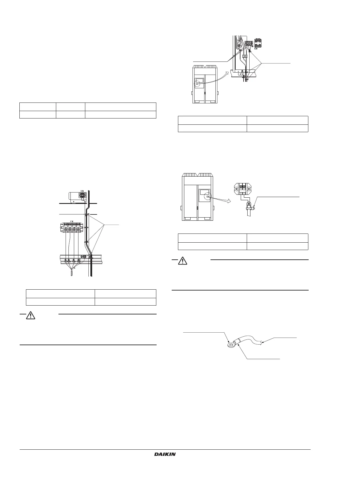
Remote operating switch wiring connections
• When installing a remote operating switch, clamp as indicated by
the following diagram:
X3M wire specifications
• For Remote switch, use non-voltage contact for microcurrent (not
more than 1mA, 12VDC)
• If the remote operating switch will be used to start and stop the unit,
set the operating switch to "REMOTE".
<Precautions for Terminal Connections>
• Be sure to use ring-type crimp-style terminals provided with insu-
lation sleeves.
• Use specified electric wires for the wiring and secure the wiring so
that external force will not be imposed on the terminal block.
• Use an appropriate screwdriver to tighten the terminal screws.
Small-sized screwdriver will damage the screw heads and cannot
tighten the screws properly.
• Do not tighten the terminal screws in excess, otherwise the screws
may be damaged.
• Refer to the following table for the tightening torque values of the
terminal screws.
• Take out the earth wire from the notch of the cup washer and lay
the wire carefully so that other wires will not be caught by the
washer. Otherwise, the earth wire may not contact sufficiently and
the earthing effect of the wire may be lost.
Z
max
(Ω)minimum S
sc
value
LRYEQ16A7Y1 0.24 1020KVA
Electric wire thickness
0.75~1.25 mm
2
Max. wiring length 130 m
Electric wire thickness
0.75~1.25 mm
2
Max. wiring length 130 m
Electric wire thickness
0.75~1.25 mm
2
Max. wiring length 130 m
Fix the wiring
X3M
2
1
Secure remote
operating switch
wiring to the resin
block using a clamp
(field supply).
Crimp-style terminal
Insulating sleeve
Power wire
4PEN448939-1A.book Page 15 Monday, September 5, 2016 7:12 PM
 Loading...