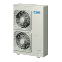
LRYEQ16A7Y1
CONVENI-PACK
4P448939-1A – 2016.07
Installation manual
6
5. PLACING THE UNIT
• Make sure the unit is installed level on a sufficiently strong base to
prevent vibration and noise.
• The base should be bigger around than the width of the unit’s legs
(66 mm), and should support the unit.
If protective rubber is to be attached, attach it to the whole face of
the base.
• The height of the base should be at least 150 mm from the floor.
•
Secure the unit to its base using foundation bolts. (Use four com-
mercially available M12-type foundation bolts, nuts, and washers.)
• The foundation bolts should be inserted 20 mm.
• When installing on a roof, make sure the roof floor is strong enough
and be sure to water-proof all work.
• Make sure the area around the machine drains properly by setting
up drainage grooves around the foundation.
Drain water is sometimes discharged from the outdoor unit when it
is running.
• When installed in a corrosive environ-
ment, use a nut with plastic washer to
prevent the nut tightening from rust..
6. REFRIGERANT PIPING
To Piping Work Contractors
• Never open the shutoff valve until the steps specified in "8. FIELD
WIRING" and "9-3 Checking of Device and Installation Condi-
tions" of piping.
• Do not use flux at the time of brazing and connecting refrigerant
pipes. Use phosphorous copper brazing filler metal (BCuP-2: JIS Z
3264/B-Cu 93P-710/795: ISO 3677), which does not require flux.
Chlorine-based flux causes piping corrosion. Furthermore, if fluo-
ride is contained, the flux will have adverse influences on the refrig-
erant piping line, such as the deterioration of refrigerating machine
oil.
Make sure the field piping and connections are not subjected to stress.
When long straight piping lengths are installed, take the necessary
countermeasures to prevent deformation due to thermal stresses.
• All field piping must be installed by a licensed refrigeration techni-
cian and must comply with relevant local and national regulations.
[Precautions for reuse of existing refrigerant piping / heat
exchangers]
Keep the following points in mind for the reuse of existing refrig-
erant piping / heat exchangers.
A malfunction may result if there is deficiency.
• Do not use the existing piping in the following cases. Perform new
piping instead.
• The piping is different in size.
• The strength of the piping is insufficient.
• The compressor of the CONVENI-PACK previously used caused
a malfunction.
An adverse influence of residual substances, such as the oxida-
tion of refrigerant oil and the generation of scale, is considered.
• If the indoor unit or outdoor unit is disconnected from the piping
for a long time.
The intrusion of water and dust into the piping is considered.
• The copper pipe is corroded.
• The refrigerant of the CONVENI-PACK previously used was
other than R410A (e.g., R404A / R507 or R407C).
The contamination of the refrigerant with heterogeneity is con-
sidered.
• If there are welded connections midway on the local piping, make
gas leakage checks on the welded connections.
• Be sure to insulate the connection piping.
The liquid and gas pipe temperatures are as follows:
Liquid pipe arrival minimum temperature
20°C (Air-conditioning side)
5°C (Refrigeration side)
Gas pipe arrival minimum temperature:
0°C (Air-conditioning side)
–20°C (Refrigeration side)
In the case of thickness insufficiency, add additional insulation
material or renew the existing insulation material.
• Renew the insulation material if the insulation material is degraded.
Keep the following points in mind for the reuse of existing heat
exchangers
• Units with insufficient design pressure (since this product is an
R410A unit) require a lower-stage design pressure of 2.5 MPa
[25 bars].
• Units for which the path to the heat exchanger has been routed so
that the flow of refrigerant is from bottom to top.
• Units with copper tubing or fan corrosion.
• Units that may be contaminated with foreign matter such as rub-
bish or other dirt.
≥100
≥100
≥100
≥100
≥100
≥100
Corner-hole
foundation
Independent
foundation
Beam
foundation
(horizontal)
Beam
foundation
(vertical)
Center of the product
Center of the product
Base form
1240
1102
729
765
(Depth of product)
631
(Inner dimension
of the base)
765 or more
(Outer dimension
of the base)
Foundation bolt point
(4-15 × 22.5)
(Unit : mm)
Base width and base bolt positions
Plastic
washers
4PEN448939-1A.book Page 6 Monday, September 5, 2016 7:12 PM
 Loading...