LRYEQ16A7Y1
CONVENI-PACK
4P448939-1A – 2016.07
Installation manual
20
*1
Set the operating switch to the "OFF" position to reset the power sup-
ply and then return the switch to the "ON" position to restart the unit.
If the problem persists, refer to the Service Manual.
• If you have changed the power wire and the transmission line, keep
the power of the indoor unit (air conditioner, refrigeration show-
case, refrigeration unit cooler) and the integrated heat control
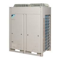
board turned on, turn off the operation switch of the outdoor units
and never fail to press the push button switch (BS5) on PCB (A1P)
in the electric accessory box (right) of the outdoor unit for at least
10 seconds (Open the inspection door (right) on the upper right
portion of the electric accessory box and operate the push button
switch (BS5) using an insulating rod). (See the right figure.)
• Refer to the Service Manual for other malfunction codes.
• Do not disconnect the power supply for 1 minute after setting the
operating switch to "ON".
Electric leak detection is performed for several seconds after the
operating switch is set to "ON" and each compressor starts oper-
ating, so disconnecting the power supply during that time will result
in a false detection.
For dealers
• After the test run is finished, check that the piping cover and front
panel are mounted.
• At the time of delivery to the customer, use the Operation Manual
and fully explain the handling of the equipment.
• For precautions at the time of delivery, refer to the provided Instal-
lation Manual for each unit as well.
13. MAINTENANCE AND SERVICE
When performing service to inverter equipment:
1. Do NOT open the electrical component box cover for 10 minutes
after the power supply is turned OFF.
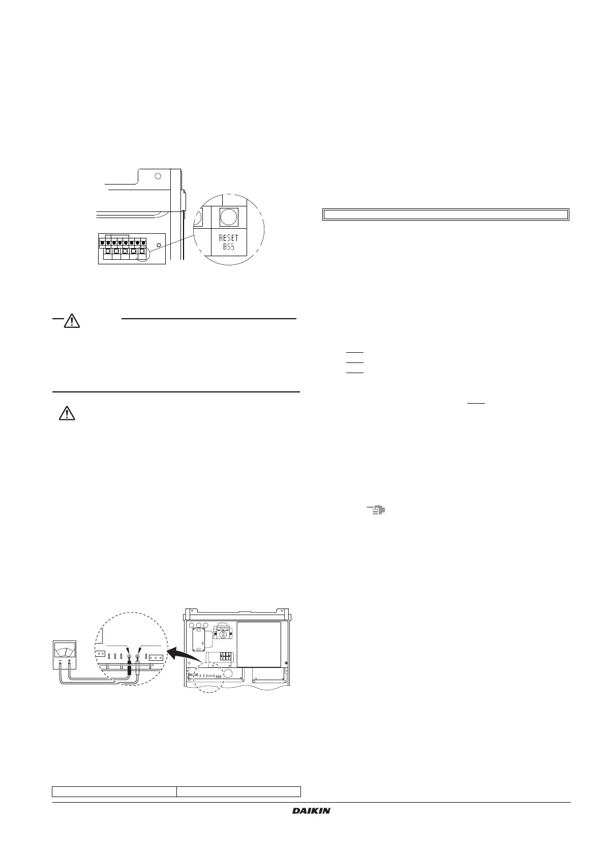
2. Measure the voltage between terminals on the terminal block for
power supply with a tester and confirm that the power supply is
shut OFF. In addition, measure points as shown in the picture
below, with a tester and confirm that the voltage of the capacitator
in the main circuit is less than 50 V DC.
3. To prevent damaging the PCB, touch a non-coated metal part to
eliminate static electricity before pulling out or plugging in connec-
tors.
4. Pull out junction connectors for the fan motors in the outdoor unit
before starting service operation on the inverter equipment. Be
careful NOT to touch the live parts. (If a fan rotates due to strong
wind, it may store electricity in the capacitator or in the main circuit
and cause electric shock.)
5. After the service is finished, plug the junction connector back in.
Otherwise the malfunction code E7 will be displayed and normal
operation will not be performed.
For details refer to the wiring diagram labeled on the back of the
service cover.
Pay attention to the fan. It is dangerous to inspect the unit while the
fan is running. Make sure to turn off the main switch and to remove
the fuses from the control circuit located in the outdoor unit.
[Checklist for yearly maintenance of the outdoor unit]
Check the following at least once a year:
• Outdoor unit heat exchanger.
The heat exchanger of the outdoor unit can get blocked up due to
dust, dirt, leaves, etc. It is recommended to clean the heat
exchanger yearly. A blocked heat exchanger can lead to too low
pressure or too high pressure leading to worse performance.
• Pressure containing parts
In case of corrosion contact your dealer.
• This product must fill the refrigerant in the field.
Calculate the amount of refrigerant replenishment according
to the following points and note the amount of the refrigerant
in a list shown below.
1. The amount of the refrigerant for the liquid piping is calculated from
the liquid piping size and the piping length of the system.
(Calculate the refrigerant additional charging quantity by rounding
off to the number in 0.1 kg.)
2. Total each piping size amount of the refrigerant.---(1)
3. The amount of the refrigerant for the indoor unit of the refrigeration
is calculated from the capacity of the connected showcase as
below table 1).
1). Total
all the refrigeration showcase capacities.
2). Total
all the freezer showcase capacities.
3). Total
all the blower coil capacities.
4). Calculate the amount of the refrigeration by the total capacities
and the table 1) below of each indoor unit.
4. The amount of the refrigerant for the each
indoor unit of the Air-
conditioner calculated from the capacity of the connected indoor
unit as below table 2).
5. Total each indoor unit amount of the refrigerant.---(2)
6. Total the amount of the refrigerant of table below(1), (2), and (3).
---(4)
7. Check sealing conditions through the sight glass at the time of test
run.
If the sight glass has not been sealed yet (due to the shortage of
refrigerant), charge additional refrigerant by 0.5 kg.
The upper limit quantity of refrigerant adjustment at the time of
the test run assumes 0.1 times of the quantity of refrigerant
which calculated from the capacity of connected indoor units.
(5)≤(2)×0.1
8. Fill the amount of the refrigerant replenishment on this label.---(5)
Junction connectors X1A, X2A, X3A, X4A
Inspection door (right)
(Upper right portion of the electric accessory box)
Method of calculating "additional refrigerant charging quantity"
4PEN448939-1A.book Page 20 Monday, September 5, 2016 7:12 PM
 Loading...