Installation manual
17
LRYEQ16A7Y1
CONVENI-PACK
4P448939-1A – 2016.07
*2 Refer to the instruction label on the front panel of the outdoor unit
(below) for the position of the service port.
• Conduct an airtight test and vacuum drying precisely through the
service ports of both liquid and gas shutoff valves.
• Use charge hoses (provided with a pushing rod each) when using
the service ports.
In case of possible water intrusion into piping
Perform the above mentioned vacuum drying for 2 hours first in the fol-
lowing cases:
The product is installed in the rainy season, there is a fear of dew con-
densation resulting in the piping because the installation work period
is long, or there is a fear of rainwater intrusion into the piping for other
reasons.
Then impose a pressure of up to 0.05 MPa with nitrogen gas (for
vacuum destruction) and vacuum the unit down to –100.7 kPa or
below for 1 hour with a vacuum pump (for vacuum drying).
Repeat vacuum destruction and vacuum drying if the pressure does
not reach –100.7 kPa or below after a minimum of 2 hours’ vacuuming.
Leave the vacuum state for 1 hour then, and check that the vacuum
gauge reading will not rise.
9-2 Thermal Insulation Work
• Be sure to perform thermal insulation of the piping after the airtight
test and vacuum drying.
•
Be sure to perform the thermal insulation of the liquid and gas pipes
in the connecting piping. Otherwise, water leakage may result.
• Be sure to insulate liquid and gas connection piping. Failure to do
so may result in water leakage. Consult the following chart as a
general guide when selecting the insulation thickness.
• Liquid pipe arrival minimum temperature
20°C (Air-conditioning side)
5°C (Refrigeration side)
Gas pipe arrival minimum temperature
0°C (Air-conditioning side)
–20°C (Refrigeration side)
• Reinforce the insulation material for the refrigerant piping accord-
ing to the environment of thermal installation. Otherwise, the sur-
face of the insulation material may result in dew condensation.
• If the dew condensation water on the shutoff valves is likely to flow
to the indoor unit side through the clearance between the insulation
material and piping because the outdoor unit is installed above the
indoor unit or for some other reasons, perform appropriate treat-
ment such as the caulking of the joints (see the illustrations below).
• Attach the cover of the piping outlet with a knock hole opened. If
there is a feature of small animals intruding through the piping out-
let, cover the piping outlet with a blocking material (field supply) on
completion of the steps of "11. REFRIGERANT REPLENISH-
MENT" (see the illustrations below).
Use the piping outlet for jobs required during the steps of "11.
REFRIGERANT REPLENISHMENT" (e.g., a job of taking in the
charge hose).
• After knocking out the holes, we recommend you remove burrs in
the knock holes and paint the edges and areas around the edges
using the repair paint.
9-3
Checking of Device and Installation Conditions
Be sure to check the followings.
<For those doing electrical work>
See "8-3 Procedure for Incoming Wiring".
1.
Make sure there is no faulty power wiring or loosing of a nut.
See "8-4 Procedure for Power Supply Wiring".
2. Has the insulation of the main power circuit deteriorated?
Measure the insulation and check the insulation is above regular
value in accordance with relevant local and national regulations.
<For those doing pipe work>
1. Make sure piping size is correct.
See "6-1 Selection of Piping Material and Size".
2. Make sure insulation work is done.
See "9-2 Thermal Insulation Work".
3. Make sure there is no faulty refrigerant piping.
See "6. REFRIGERANT PIPING".
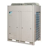
Position of instruction label
Label
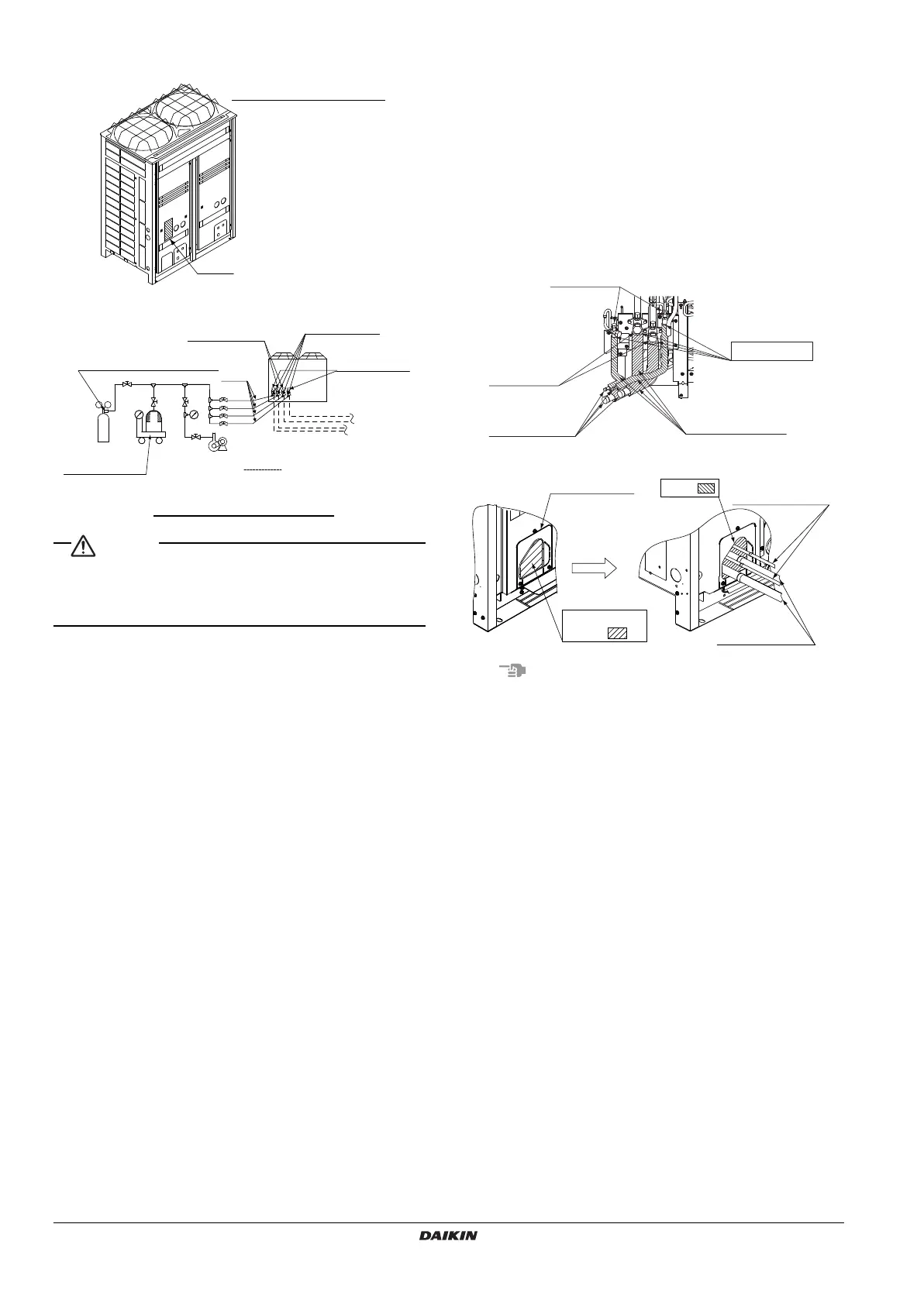
Pressure-reducing valve
Nitrogen
Used for refrigerant
replenishment
Tank
(with siphon)
Meter
Vacuum pump
Field pipingsNote:
Connection procedure for gauge
manifold and vacuum pump
R410A
To Air-conditioning
indoor unit
To Refrigeration
indoor unit
Shutoff valve
service port
Liquid side
shutoff valve
Outdoor unit
Gas side
shutoff valve
Valve
Charge
hose
Gas side
shutoff valve
Indoor/Outdoor
interunit piping
Insulation material
Caulking, etc.
Liquid side piping
Block
Gas side piping
Open a knock
hole at
Piping lead-out
hole lid
4PEN448939-1A.book Page 17 Monday, September 5, 2016 7:12 PM
 Loading...