LRYEQ16A7Y1
CONVENI-PACK
4P448939-1A – 2016.07
Installation manual
4
1 Manuals and labels
2 Accessory pipes (Installed on bottom frame)
2-3 Indoor Unit Constraints (Refrigeration and
Freezer)
• The design pressure for the indoor unit is 2.5 MPa or more.
• Install an R410A expansion valve on each indoor unit.
The following expansion valve types are allowed:
• Mechanical thermostatic expansion valves: install an R410A
solenoid valve on the primary side of the mechanical thermo-
static expansion valve (maximum operating differential pres-
sure of 3.5 MPa (35 bars) or over) for each individual unit.
• Electronic expansion valve:
•Proportional type: Only allowed if the controller can close the
valve within 5 seconds from fully open to fully closed. Some
proportional valves may bleed. In this case, install an R410A
solenoid valve on the primary side of the expansion valve
(Max. operating differential pressure of 3.5 MPa [35 bars] or
over) for each indoor unit.
• Insulate the feeler block of the mechanical thermostatic expansion
valve.
• Install a filter on the primary side of the solenoid valve described
above for each indoor unit. Determine the filter mesh count based
on the size specified by the solenoid valve and mechanical thermo-
static expansion valve being used. In case a pulsating type expan-
sion valve is used, no filter can be installed near the expansion
valve.
• Route the path to the indoor unit heat exchanger so that the flow of
refrigerant is from top to bottom.
• When installing a number of indoor units, be sure to install them at
the same level.
• Use either off-cycle defrosting or electric heater defrosting as the
defrosting type. Hot-gas defrosting models cannot be used.
2-4 Indoor Unit Constraints (Air Conditioning)
Indoor unit models to be connected are listed in the table below.
• Indoor unit for air conditioning that can be connected:
Restrictions
1. The minimum air conditioning total capacity...8 HP
(Capacity class: 200)
2. The maximum air conditioning total capacity...12 HP
(Capacity class: 300)
3. The maximum indoor unit connection number...6 or less
1. The indoor unit for air conditioning does not operate until its
cooling capacity exceeds 4 HP. For this reason, do not connect
remote controllers individually to the indoor unit for less than 4 HP
when using heating/cooling operations. The indoor unit for air
conditioning does not operate until the capacity of the indoor unit for
air conditioning of CONVENI-PACK exceeds 3 HP on heating. For
this reason, do not connect the remote controller individually to the
indoor unit for less than 3 HP when operating the heating only
machine.
2. Set up the indoor units for the air conditioning controlled by the
same remote controller in the same space.
3. SELECTION OF LOCATION
Select a location for installation that meets the following conditions.
Get the customer’s permission.
1. There is no danger of fire due to leakage of inflammable gas.
2. Select the location of the unit in such a way that neither the dis-
charged air nor the sound generated by the unit disturb anyone.
3. The foundation is strong enough to support the weight of the unit
and the floor is flat to prevent vibration and noise generation.
4. The piping length between the outdoor unit and the indoor unit may
not exceed the allowable piping length. (Refer to
"6. REFRIGERANT PIPING")
5. Locations where the unit’s suction vent and outlet vent do not gen-
erally face the wind.
Wind blowing directly into the suction or outlet vents will interfere
with the unit’s operation.
If necessary, install some kind of obstruction to block the wind.
6. The space around the unit is adequate for servicing and the mini-
mum space for air inlet and air outlet is available.
(See the "Installation Space Examples" for the minimum space
requirements.)
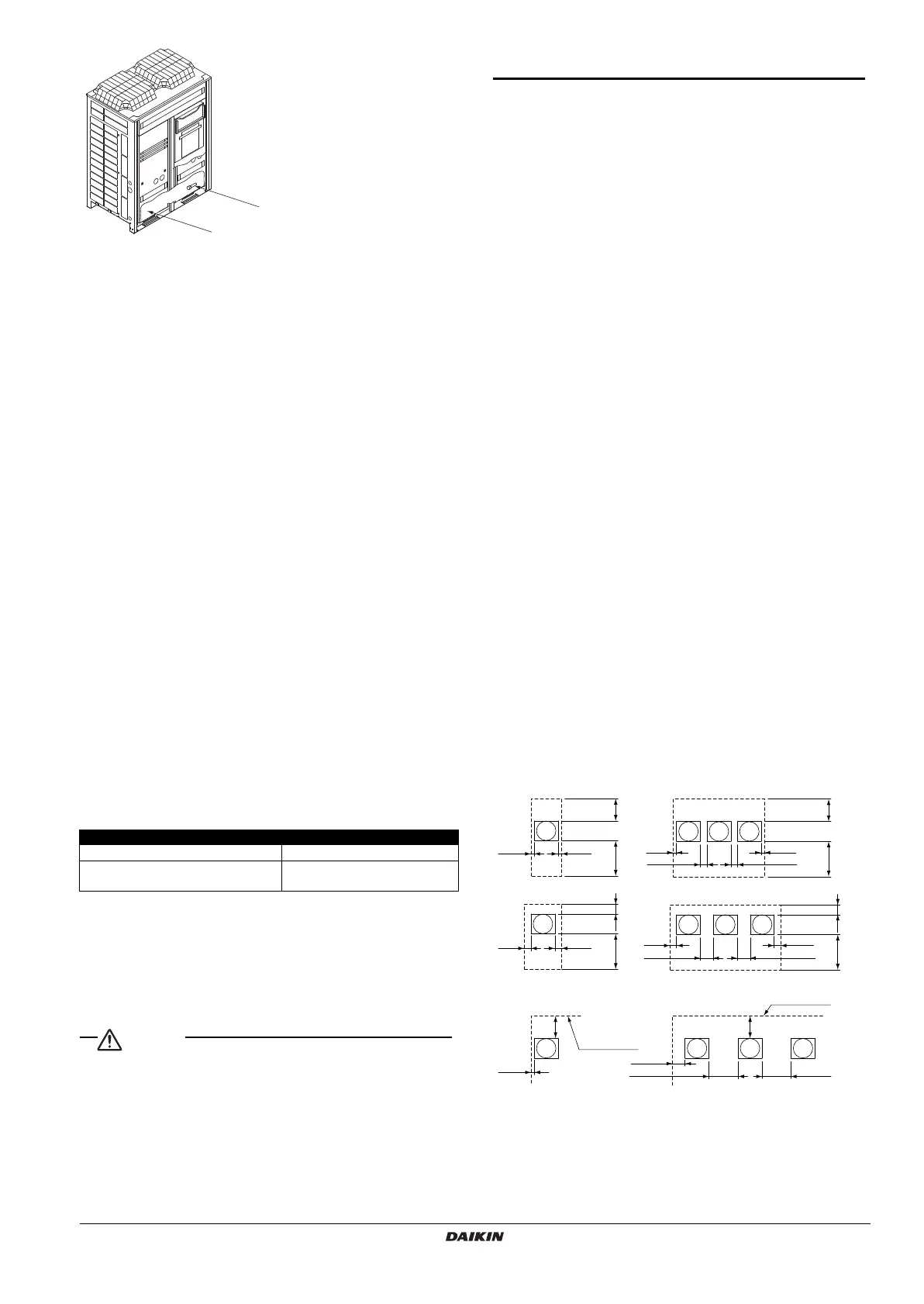
Installation Space Examples
• The installation space requirement shown in the following figure is
a reference for cooling operation when the outdoor temperature is
32°C.
If the design outdoor temperature exceeds 32°C or the heat load
exceeds maximum capacity in all the outdoor unit, take an even
large space on the intake shown in the following figure.
• During installation, install the units using the most appropriate of
the patterns shown in the following figure for the location in ques-
tion, taking into consideration human traffic and wind.
• If the number of units installed is more than that shown in the pat-
tern in the following figure, install the units so there are no short cir-
cuits.
• As regards space in front of the unit, consider the space needed for
the local refrigerant piping when installing the units.
• If the work conditions in the following figure do not apply, contact
your dealer or Daikin directly.
NOTE) For Patterns 1 and 2
• Wall height for front side no higher than 1500 mm.
• Wall height on the suction side no higher than 500 mm.
• Wall height for sides – no limit
• If the height is exceeded the above, calculate h1 and h2 shown
in the figure below and add h1/2 to the service space of front
side and h2/2 to the service space of suction side.
Capacity class
50~80 100~250
Individual control by remote
controller is NOT allowed.
Individual control by remote
controller is allowed.
2
1
≥10 ≥10
≥10
≥20
≥10
≥20
≥50
≥100
≥50
≥100
≥200
≥400 ≥400
≥50 ≥50
≥200
≥300
≥300
≥300≥500
≥100≥500
≥300
≥500≥100≥500
<
When installed as a single unit
>
(Pattern 1) NOTE)
(Pattern 2) NOTE) (Pattern 2) NOTE)
(Pattern 3) (Pattern 3)
(Pattern 1) NOTE)
<
When installed in serial
>
Front
side
Front side
Front side
Front side
Front
side
Front side
No limit to
wall height
No limit to
wall height
Service space
of suction side
Service space
of front side
Service space
of suction side
Service space
of front side
Service space
of suction side
Service space
of front side
Service space
of suction side
Service space
of front side
4PEN448939-1A.book Page 4 Monday, September 5, 2016 7:12 PM
 Loading...