Compressor Control for Maverick II
VFD Compressor Operation
When a MPS is equipped with the VFD compressor option
there are two refrigeration circuits, one VFD controlled
compressor with up to 3 xed speed compressors depending
on unit model. The VFD compressor must always be the “lead”
circuit or rst one on and last one off.
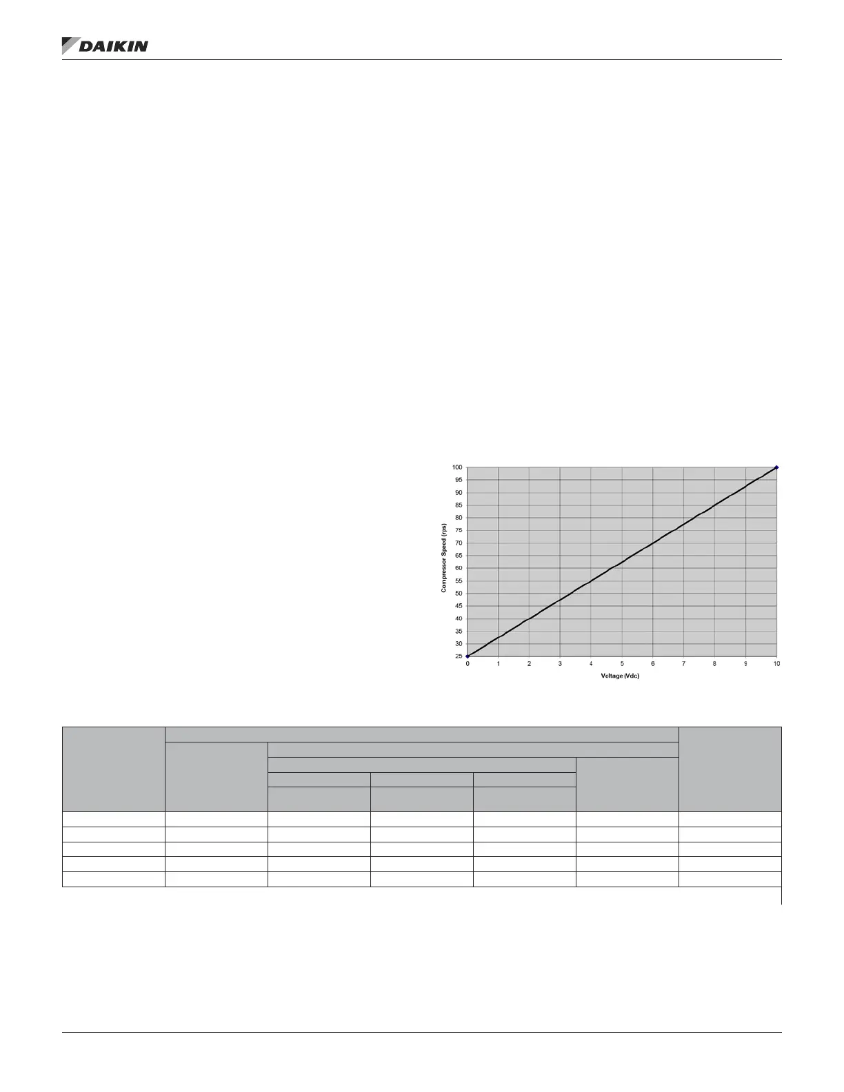
VFD compressor modulation is controlled by an analog signal
(0 – 10 Vdc) from the unit controller. Refer to Figure 101. The
minimum VFD compressor speed is 25 rps (1500 rpm) and the
maximum VFD compressor speed is 100 rps (6000 rpm), but
the minimum and maximum limits per unit may vary depending
on operating conditions and unit model size.
The VFD compressor is a 4 pole motor design that operates off
a frequency signal from the VFD between 50Hz and 200Hz.
At Start-up the VFD compressor will automatically ramp up to
50 rps for rst 10 seconds for lubrication requirements.
Crankcase heating for VFD Compressor model VZH-088 is
performed by the VFD via DC-holding current through the
motor windings.
VFD compressor modulation is additionally monitored and
adjusted in order to maintain operation within the approved
compressor operating envelope.
If the VFD compressor were to become inoperative, any other
compressors on the VFD circuit will be disabled. The unit can
continue to operate on the remaining xed speed compressors
of the non-VFD circuit until the unit can be serviced.
When the VFD compressor is at its maximum speed and
more capacity is required, a xed speed compressor is started
while the VFD compressor is reduced to minimum speed at
which point it resumes modulating to maintain the discharge
temperature. When the VFD compressor is at its minimum
speed and less capacity is required, a xed speed compressor
is turned off while the VFD compressor is increased to
maximum speed at which point it resumes modulating to
maintain discharge temperature.
Figure 18: VFD Compressor Modulation Signal
Table 52: VFD Compressor Modulation Ranges
MPS Unit Model
VFD Modulation Range
OilBoostrps/
OilBoostV*
VFD Min rps/
VFD Min V
VFD Max rps
VFD and Fixed Comp(s) On
VFD Comp Only
VFDMax rps/
VFDMaxV
1 Fixed On 2 Fixed On 3 Fixed On
VFD1Max rps/
VFD1MaxV
VFD2Max rps/
VFD2MaxV
VFD3Max rps/
VFD3MaxV
026 39 rps / 0 Vdc 60 rps / 4.0 V 55 rps / 4.0 V NA 70 rps / 6.0 V 70 rps / 4.0 V
030 39 rps / 0 Vdc 100 rps / 8.7 V 80 rps / 7.3 V NA 100 rps / 10.0 V 100 rps / 7.3 V
035 39 rps / 0 Vdc 100 rps / 8.7 V 80 rps / 7.3 V NA 100 rps / 10.0 V 100 rps / 7.3 V
040 39 rps / 0 Vdc 85 rps / 8.0 V 85 rps / 8.0 V 80 rps/ 7.3 V 100 rps / 10.0 V 100 rps / 7.3 V
050 39 rps / 0 Vdc 85 rps / 8.0 V 85 rps / 8.0 V 80 rps/ 7.3 V 100 rps / 10.0 V 100 rps / 7.3 V
* High and Low Oil Boost are explained on page 136
operaTor’s guIde
www.DaikinApplied.com 117 OM 920-6 • MICROTECH UNIT CONTROLLER