4 Daikin IM 1019
Installation Instructions
Thermostat Model and Part Number
Optional Sensors/Kits
In addition to the T180 thermostat, Daikin offers optional
sensors for occupancy detection (page 14 and page 15) and
10K pipe sensor page 12) that can be ordered and used in
conjunction with the thermostat. Use the associated kit
number(s) provided in Table 3 when ordering.
Installing, Mounting and Wiring
the Thermostat
The thermostat should be used indoors only. It should be
mounted on an inner wall in a location with freely circulating
air, and where it will be responsive to changes in room
temperature. Avoid mounting near heat generating appliances
(i.e. TV, heater, refrigerator), or in direct sunlight.
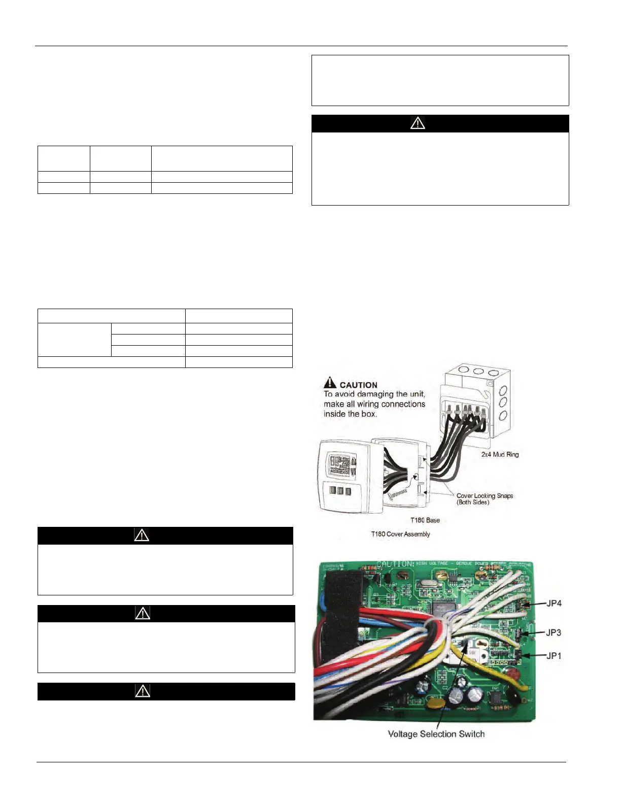
The thermostat base mounts to a field provided 4" × 4" outlet
box with a 2" × 4" horizontal mud ring. The thermostat cover
assembly mounts to the thermostat base.
.
1 Disconnect power before installing or servicing.
2 Run line voltage wiring (and low voltage wiring if
applicable) into the field provided outlet box and mud
ring (Figure 2).
3 Locate all connections within the mud ring/connection
box and wire nut all unused wires.
4 Remove the thermostat cover assembly from its base to
gain access to the circuit board (Figure 3).
Figure 2: Mounting the Thermostat
Figure 3: Circuit Board
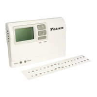
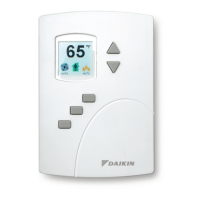
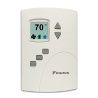
Daikin offers two different 7-Day Programmable Digital
Heating/Cooling Thermostat with constant fan or Fan cycled,
On/Off Valve Control depending on the fan speed control
used (See Table 2).
.
Table 2: Thermostat Model and Part Number
Model
Number
Part
Number
Fan Speed Control
TA180-001 910119110 3-speed fan control
TB180-001 910119111 Staged fan control
Table 3: Sensor Model and Kit Numbers
Sensor Model Number Daikin Part Number
Occupancy
Detection
Sensor
SB200-001 6677877311
SD200-001 6677877411
SD200-002 6677877511
10K Pipe Sensor 107201601
CAUTION
Before applying power, the voltage selection switch must be in
the appropriate position. Failure to select the correct voltage
can cause thermostat malfunction or permanently damage the
thermostat.
CAUTION
To use a remote sensor on units with local sensing capability,
remove jumper JP1 to disable local sensing. Failure to remove
JP1 can cause improper operation of the thermostat with a
remote probe installed.
CAUTION
• Use copper wire only. Insulate or wire nut all unused leads.
• Avoid electrostatic discharge to the thermostat.
• Failure to do so can cause thermostat malfunction or
permanently damage the thermostat.
DANGER
Hazardous voltage. Combined load current is not to exceed 20
amps. Mount only to a grounded metallic box.
Low voltage wiring is Class 2. To avoid electrical shock or
Damage to equipment, disconnect power before installing or
servicing. Failure to follow these instructions will result in death
or serious injury