Daikin IM 1019 5
Installation Instructions
5 On the circuit board, set the voltage selection switch
(Figure 3) to the appropriate position prior to application
of power.
• 24V = 24 VAC
• 110-277 V = 120, 240 or 277 VAC
Note: The circuit board is shipped with the voltage
selection switch in the 110-227 V position. For 24
VAC use, the switch must be in the 24 V position
6
The circuit board is also equipped with configuration
jumpers (JP1, JP3, and JP4 in Figure 3). Depending on
the application, it may be necessary to reconfigure the
following jumpers:
JP1 Jumper Selection – Remote Temperature Sensor
Local Sensing – Install JP1
Remote Sensing – Remove JP1 – Accessory sensors are
available in standard 60" lengths but can be extended to
meet application requirements.
JP3 Jumper Selection – HVAC Setback Systems
The JP3 jumper allows the T180 to be configured for
Setback, Occupancy Detection or Door Switch Only
Occupancy Operations. For further descriptions of these
conditions please see the Technical and Application
Notes‚ page 12.
• Setback Operation - Remove JP
3
•
Occupancy Detection - Install
JP3
•
Door Switch Only - Install JP3
JP4 Jumper Selection – 2 or 4 Pipe Operation
Connection of a pipe sensor will change the operation of
the outputs as shown in Table 4. (See Technical Notes for
further information on Pipe Sensor Operation‚ page 12)
• 2-Pipe Operation - Install JP4 - The thermostat will per-
manently disable the Secondary Output and disables sys-
tem and fan invalid modes.
• 4-Pipe Operation - Remove JP4 - Both the Main Output
(COOL) and Secondary Output (HEAT) will be avail-
able.
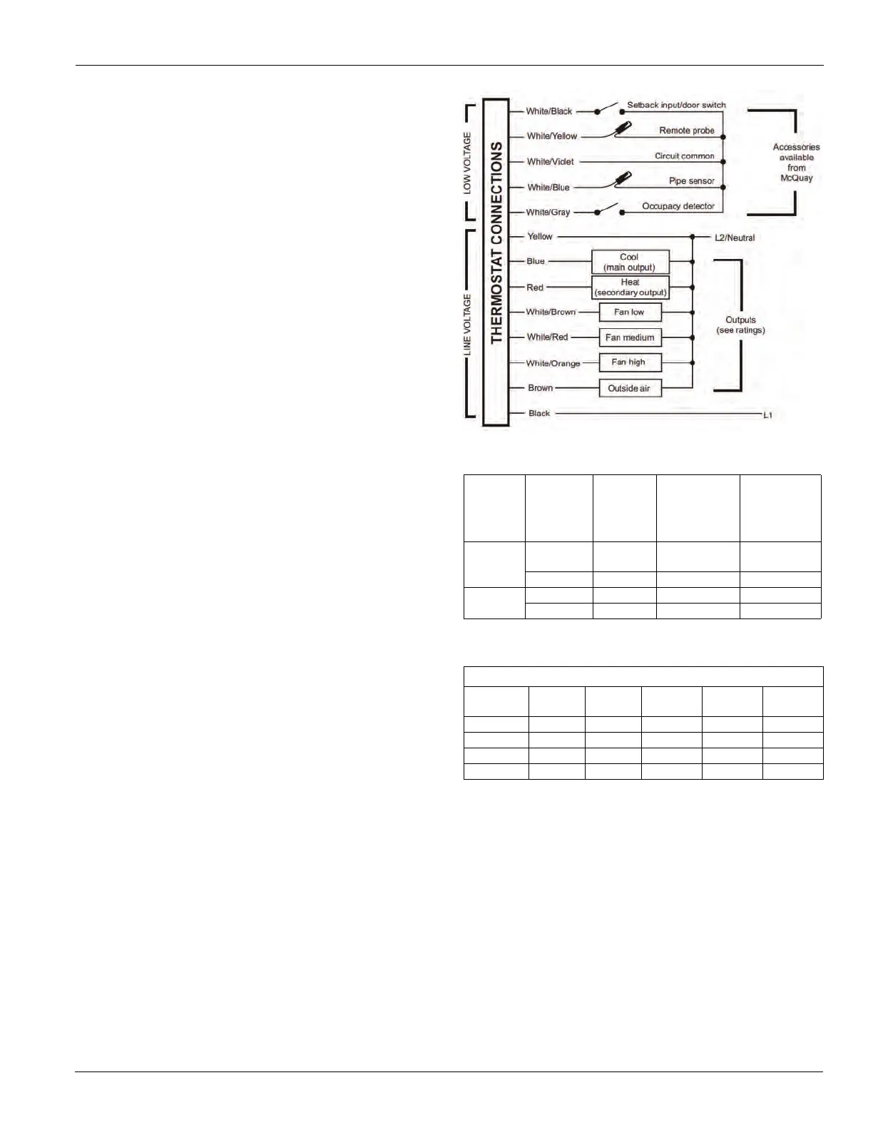
7 Connect the color coded thermostat wires (Figure 4) to
the line voltage wires located in the mud ring/connection
box and secure the connections with wire nuts.
8 Install the thermostat base to the mud ring/outlet box
using two furnished mounting screws. Tighten the
screws evenly but do not over tighten.
Note: An output ratings chart (Table 5) is located on the
inside of the base.
9
With the base now secured, verify that the circuit board
is firmly snapped into the cover and is not dislodged.
10 Install the cover assembly to the base, pressing firmly to
engage the cover locking snaps.
Figure 4: Wiring Diagram
Table 4: Jumper Activation
JP4
Section
Pipe
Sensor
Water
Temp
Aqua
Stat
Main
Output
(Blue Wire)
Secondary
Output
(Red wire)
2-Pipe
JP4-ON
Cold Open
Cooling
Only
Disabled
Hot Closed Heating Only Disabled
2-Pipe
JP4-OFF
Cold Open Cooling Heating
Hot Closed Heating Only Disabled
Note: *Fan will not cycle on for disabled modes.
Table 5: Output Ratings
Output Ratings
Voltage FLA LRA
RES
AMPS
PILOT
DUTY
HP
24 VAC NA NA NA 24 VA NA
120 VAC 5.8 34.8 6.0 125 VA ¼
240 VAC 2.9 17.4 5.0 125 VA ¼
277 VAC 2.4 14.4 4.2 125 VA ¼
Combined Load Current Not to Exceed 20 Amps