Field Settings SiBE121135_A
255 Trial Operation and Field Settings
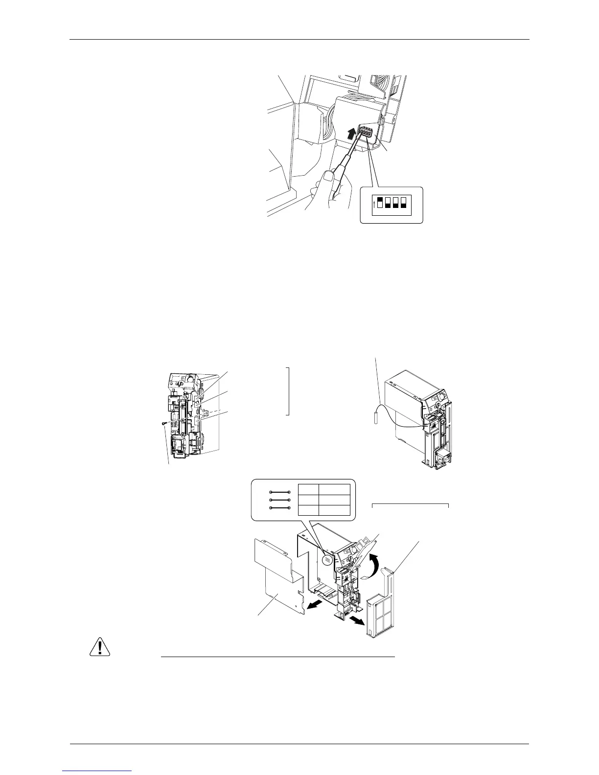
(3)Turn on the DIP switch [S2W-1] on the service PCB.
∗ Keep the other switches as factory setting (OFF).
FVXS Series
1) Remove the front grille.
2) Lift the sensor PCB fixing plate and remove the front shield plate.
3) Disconnect the connectors [S1] [S41] [S42].
4) Remove the electric box (1 screw).
5) Pull out the indoor heat exchanger thermistor.
6) Remove the shield plate (8 tabs).
7) Cut the address setting jumper JA on the indoor unit PCB.
Caution Replace the PCB if you accidentally cut a wrong jumper.
Jumpers are necessary for electronic circuit. Improper operation may occur if you cut any of
them.
1 2 3 4
OFF
ON
Service PCB
(R14630)
Connector [S42]
Connector [S41]
Connector [S1]
4) Remove the screw.
5) Indoor heat exchanger
thermistor
3)
6) Shield plate
(R17290)
Sensor
PCB fixing
plate
JC
JA
JB
JA
EXIST
CUT
Address
1
2
2)
Front shield
plate