Indoor Unit Installation (3)
1) Do not use spliced wires, strand wires, extension cords, or starburst connections, as they may cause overheating,
electrical shock, or fire. Follow all Local, and State electrical codes.
2) Do not use locally purchased electrical parts inside the product. (Do not overload the circuit by adding drain pump
or other electrical equipment to unit terminals.) Doing so may cause electric shock or fire.
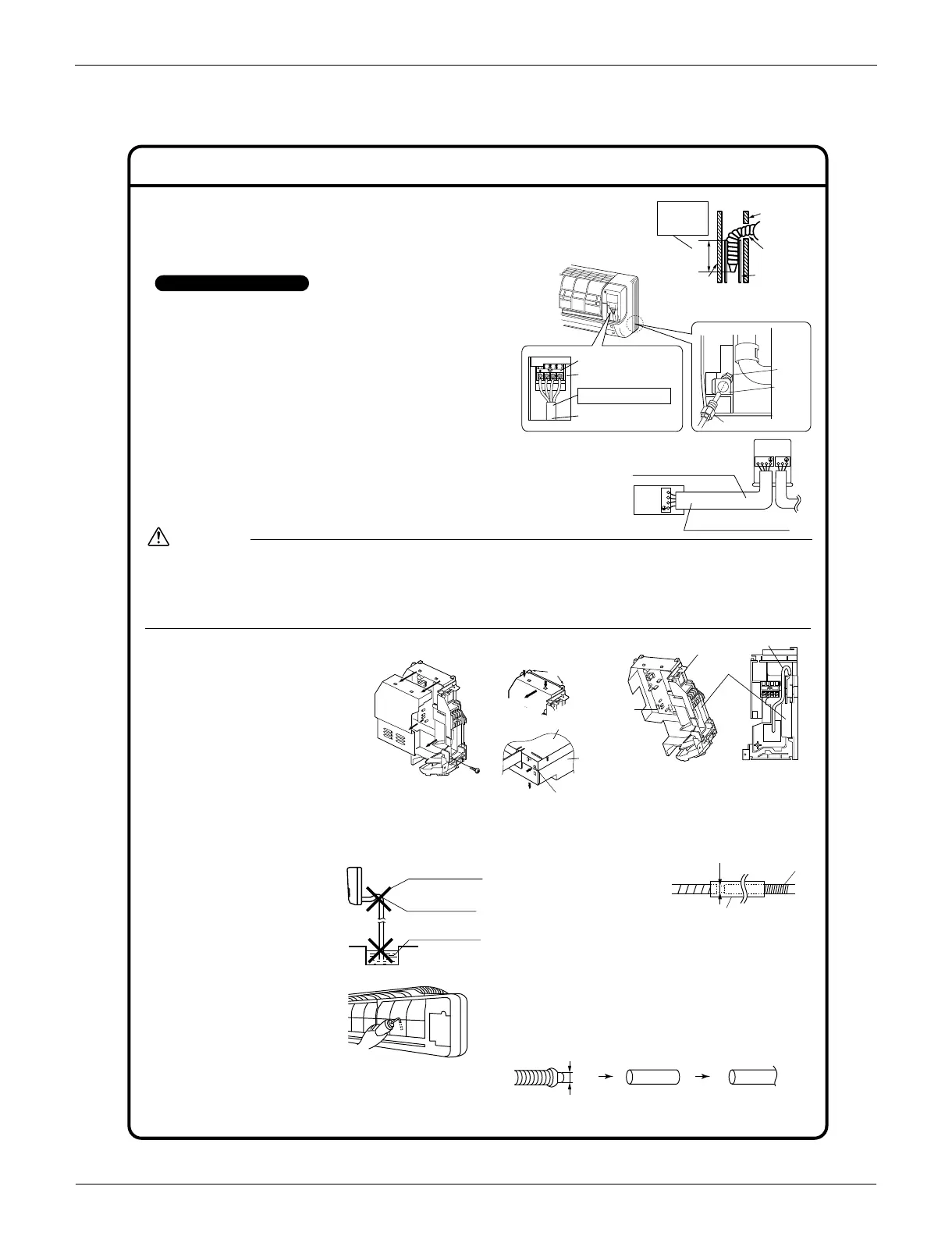
3) When carrying out wiring connection, take care not to pull at the conduit.
WARNING
5. When connecting to an HA system.
1)
Remove the front grille. (2 screws)
2) Remove the electrical
wiring box. (1 screw)
3)
Remove the metal plate
electrical wiring cover. (4 tabs)
4)
Attach the connection cord to
the S21 connector and pull
the harness out through the
notched part in the figure.
5)
Replace the electrical wiring cover as it was, and
pull the harness around, as shown in the figure.
6. Drain piping.
1) Connect the drain hose,
as described right.
2) Remove the air filters
and pour some water
into the drain pan to
check the water flows
smoothly.
3) If the drain hose
requires an
extension, procure
one locally.
Be sure to thermally
insulate the indoor
section of the extension hose.
4)
When connecting a rigid polyvinyl chloride pipe
(nominal diameter 1/2 inch (13mm)) directly to the drain
hose attached to the indoor unit as with embedded
piping work, use any commercially available drain
socket (nominal diameter 1/2 inch (13mm)) as a joint.
4. Wiring.
With a Multi indoor unit , install as described in the
installation manual supplied with the Multi outdoor unit.
1) Strip wire ends. (9/16 inch (15mm))
2)
Match wire colors with terminal numbers on indoor and
outdoor unit’s terminal blocks and firmly screw wires to
the corresponding terminals.
3) Connect the ground wires to the corresponding
terminals.
4) Pull wires to make sure that they are securely
latched up.
5) In case of connecting to an adapter system.
Run the remote controller cable and attach the S21 connector as the
illustration above.
6)
Shape the wires so that the service lid fits securely, then close service lid.
3-3. Wall embedded piping.
• Insert the drain hose to this depth so it won
’
t be
pulled out of the drain pipe.
The drain hose should
be inclined downward.
No trap is permitted.
Do not put the end
of the hose in water.
Indoor unit
drain hose
φ11/16”
(φ18mm)
Extension drain hose
Heat insulation tube
(Field supply)
Drain hose supplied with
the indoor unit
Commercially available drain socket
(nominal diameter 1/2 inch (13mm))
Commercially available rigid polyvinyl
chloride pipe
(nominal diameter 1/2 inch (13mm))
φ11/16”
(φ18mm)
Screw
HA cord
HA connector
(S21)
Ta b
Ta b
Push
Slide
Push
Metal plate
electrical cover
Ta b
Push
Main body
Notched part
Replace the electrical
wiring cover as it was,
and pull the harness
around, as shown
in the figure.
Attach the connection cord to
the S21 connector and pull the
harness out through the
notched part in the figure.
3)
Remove the metal
plate electrical
wiring cover.
3
2
1
123
L
1
L
2
When wire length exceeds
33ft (10m), use AWG14 wires.
Use AWG16 or AWG14 wire
for the Interconnecting wires.
Outdoor unit
Indoor
unit
Use the specified wire type.
Shape wires so that the service
lid will fit securely.
Electrical component box
Terminal block
123
Conduit
mounting
plate
Conduit
Lock nut
Back
Inner wall
Vinyl chloride
drain pipe
(VP-30)
Drain hose1-15/16”
(50mm)
or more
Insert drain hose
to this depth so
it won’t be pulled
out of drain pipe.
Outer wall
5)4)
 Loading...
