Outdoor Unit EDUS121131
292 Installation Manual
Test Run and Final Check
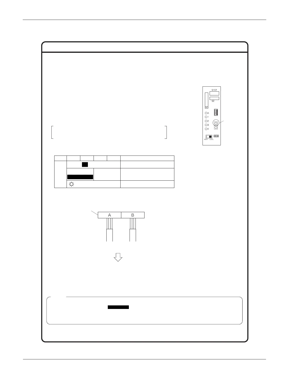
Wiring error
check switch
(SW3)
Service PC-board
LED
Status
1 2 3 4
All Flashing Automatic correction impossible
Automatic correction completed
Abnormal stop [NOTE. 4]
Message
Flashing
One after another
OFF [NOTE.1]
(One or more of LEDs 1 to 4 are ON)
Terminal block
Wiring error check
LED lighting sequence after a wiring correction.
Order of LED flashing: 2 ➝ 1
From Room B
to the “living room”
From Room A
to the “bedroom”
Wiring correct example
∗ The figure at left shows branch wiring.
(1) LED 3 and 4 are not displayed.
(2) If the outside air temperature is 41°F or less , the wiring error check function will not operate.
(3) After wiring error check operation is completed, LED indication will continue until ordinary operation starts.
This is normal.
(4) Follow the product diagnosis procedures. (Check the nameplate on the stop valve cover.)
NOTE
● Before starting the test run, measure the voltage at the primary side of the safety breaker.
● Check that all liquid and gas stop valves are fully open.
● Check that piping and wiring all match. The wiring error check can be conveniently used for underground wiring and
other wiring that cannot be directly checked.
Wiring error check
● This product is capable of automatic correction of wiring error.
Press the “wiring error check switch” on the outdoor unit service
monitor print board. However, the wiring error check switch will not
function for one minute after the safety breaker is turned on, or
depending on the outside air conditions (See NOTE 2.). Approximately
10~15 minutes after the switch is pressed, the errors in the
connection wiring will be corrected.
The service monitor LEDs indicate whether or not correction is
possible, as shown in the table below. For details about how to read
the LED display, refer to the service guide.
If self-correction is not possible, check the indoor unit wiring and
piping in the usual manner.
 Loading...
