19 | Electrical installation
Installer and user reference guide
111
REYQ8~20+REMQ5U7Y1B
VRV IV+ heat recovery
4P561154-1A – 2020.10
NOTICE
Only applicable if the power supply is three‑phase, and the compressor has an ON/
OFF starting method.
If there exists the possibility of reversed phase after a momentary black out and the
power goes on and off while the product is operating, attach a reversed phase
protection circuit locally. Running the product in reversed phase can break the
compressor and other parts.
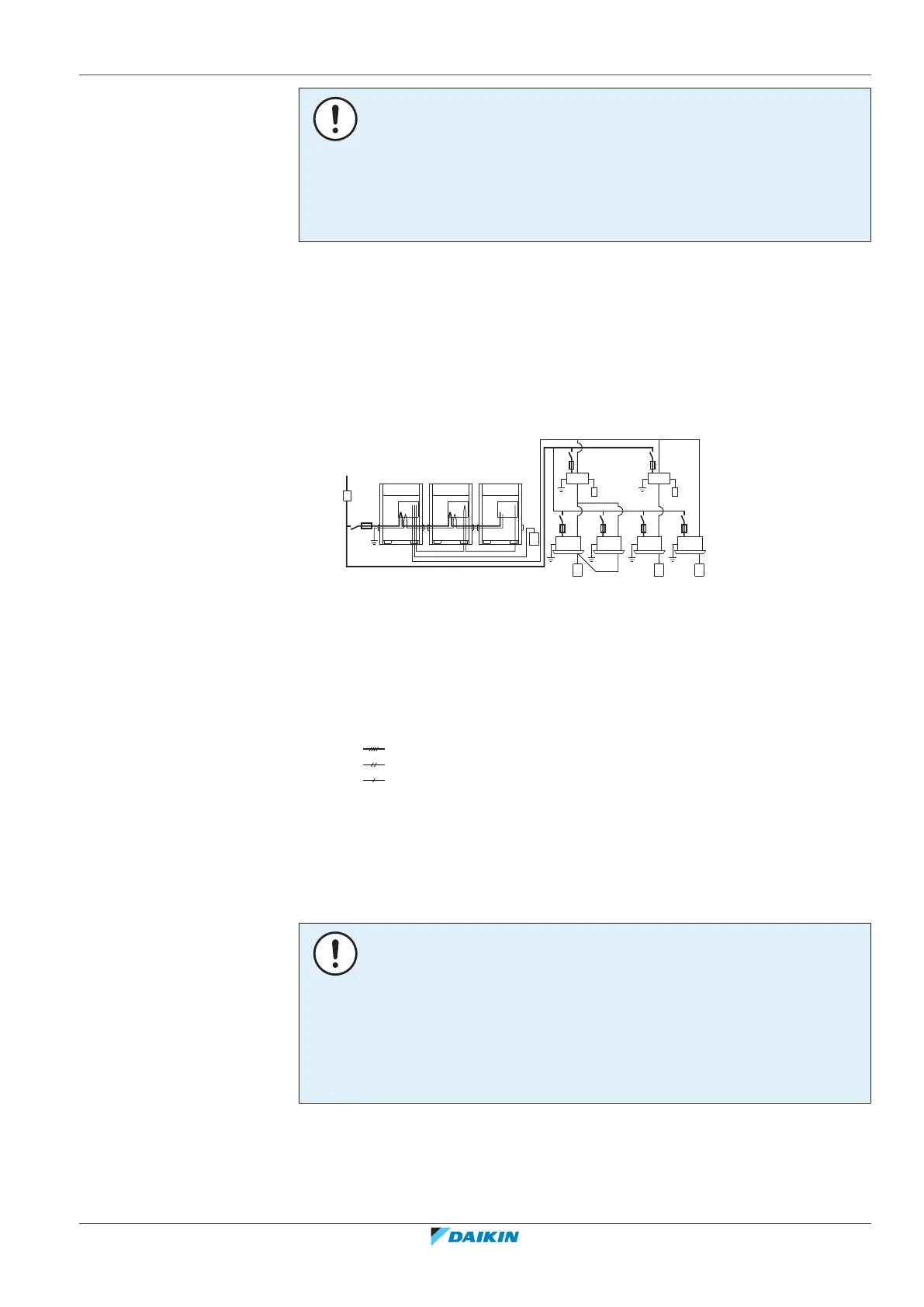
19.1.2 Field wiring: Overview
Field wiring consists of:
▪ power supply (including earth),
▪ DIII transmission wiring between communication box and outdoor unit,
▪ RS‑485 transmission wiring between communication box and monitoring system.
Example:
a Field power supply (with earth leakage protector)
b Main switch
c Earth connection
d Outdoor unit
e Indoor unit
f User interface
g BS unit
h Cool/heat selector
i Circuit breaker
j Fuse
Power supply 3N~50Hz
Power supply 1~50Hz
Earth wiring
19.1.3 About the electrical wiring
It is important to keep the power supply and the transmission wiring separated
from each other. In order to avoid any electrical interference the distance between
both wiring should always be at least 25mm.
NOTICE
▪ Be sure to keep the power line and transmission line apart from each other.
Transmission wiring and power supply wiring may cross, but may not run parallel.
▪ Transmission wiring and power supply wiring may not touch internal piping
(except the inverter PCB cooling pipe) in order to avoid wire damage due to high
temperature piping.
▪ Firmly close the lid and arrange the electrical wires so as to prevent the lid or
other parts from coming loose.
The transmission wiring outside the unit should be wrapped and routed together
with the field piping.
Field piping can be routed from front or bottom of the unit (going left or right).
Refer to "To route the refrigerant piping"[484].