19 | Electrical installation
Installer and user reference guide
117
REYQ8~20+REMQ5U7Y1B
VRV IV+ heat recovery
4P561154-1A – 2020.10
c Tie wrap. Fix to factory-mounted low voltage wiring.
d Tie wrap.
(a) Knockout hole has to be removed. Close the hole to avoid small animals or dirt from
entering.
X1A
c
d
a b a b
5~12 HP 14~20 HP
Fix to the indicated plastic brackets using field supplied clamping material.
a Wiring between the units (indoor-outdoor) (F1/F2 left)
b Internal transmission wiring (Q1/Q2)
c Plastic bracket
d Field supplied clamps
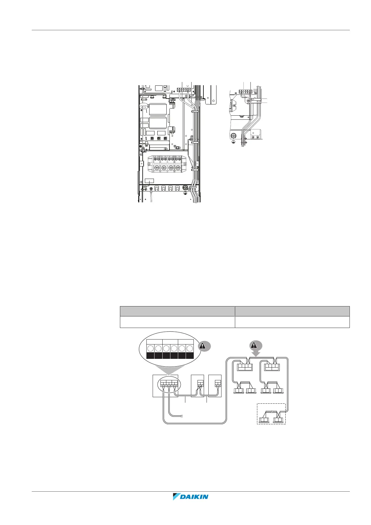
19.3 To connect the transmission wiring
The wiring from the indoor units must be connected to the F1/F2 (In‑Out)
terminals on the PCB in the outdoor unit.
Tightening torque for the transmission wiring terminal screws:
Screw size Tightening torque (N•m)
M3.5 (A1P) 0.8~0.96
F1 F2 F1 F2 Q1 Q2
F1 F1F2 F2 Q1Q2
g
e
TO IN/D UNIT
TO OUT/D UNIT TO MULTI UNIT
A1P
Q1 Q2
A1P
Q1 Q2
A1P
a b c
d
f
F1 F2 F1 F2 F1 F2 F1 F2
TO IN/D
UNIT
TO OUT/D
UNIT
TO IN/D
UNIT
TO OUT/D
UNIT
F1 F2 F1 F2 F1 F2 F1 F2
F1 F2 F1 F2
j
ii
hh
e
a Unit A (master outdoor unit)
b Unit B (slave outdoor unit)
c Unit C (slave outdoor unit)
d Outdoor unit PCB (A1P)
e Master/slave transmission (Q1/Q2)
f Outdoor/indoor transmission (F1/F2)
g Outdoor unit/other system transmission (F1/F2)
h BS unit
i Indoor unit