26 | Technical data
Installer and user reference guide
163
REYQ8~20+REMQ5U7Y1B
VRV IV+ heat recovery
4P561154-1A – 2020.10
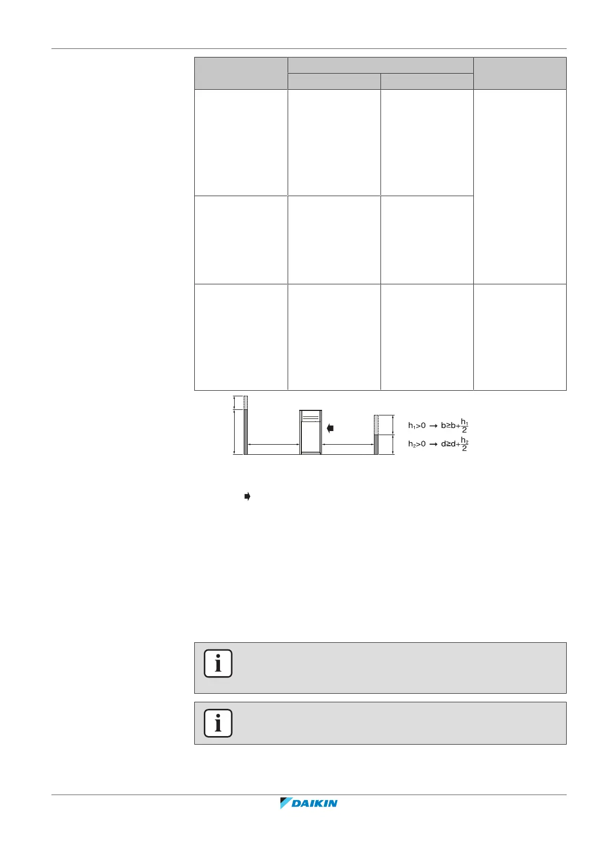
Layout A+B+C+D A+B
Possibility 1 Possibility 2
3 a≥10mm
b≥300mm
c≥10mm
d≥500mm
e≥20mm
f≥600 mm
a≥50mm
b≥100mm
c≥50mm
d≥500mm
e≥100mm
f≥500mm
—
4 a≥10mm
b≥300mm
c≥10mm
d≥500mm
e≥20mm
a≥50mm
b≥100mm
c≥50mm
d≥500mm
e≥100mm
5 a≥10mm
b≥500mm
c≥10mm
d≥500mm
e≥20mm
f≥900mm
a≥50mm
b≥500mm
c≥50mm
d≥500mm
e≥100mm
f≥600mm
—
ABCD Sides along the installation site with obstacles
F Front side
Suction side
▪ In case of an installation site where sides A+B+C+D have obstacles, the wall
heights of sides A+C have no impact on service space dimensions. Refer to the
figure above for impact of wall heights of sides B+D on service space dimensions.
▪ In case of an installation site where only the sides A+B have obstacles, the wall
heights have no influence on any indicated service space dimensions.
▪ The installation space required on these drawings are for full load heating
operation without considering possible ice accumulation. If the location of the
installation is in a cold climate, then all dimensions above should be >500mm to
avoid accumulation of ice in between the outdoor units.
INFORMATION
The service space dimensions in above figure are based on cooling operation at 35°C
ambient temperature (standard conditions).
INFORMATION
Further specifications can be found in the technical engineering data.