18 | Piping installation
Installer and user reference guide
82
REYQ8~20+REMQ5U7Y1B
VRV IV+ heat recovery
4P561154-1A – 2020.10
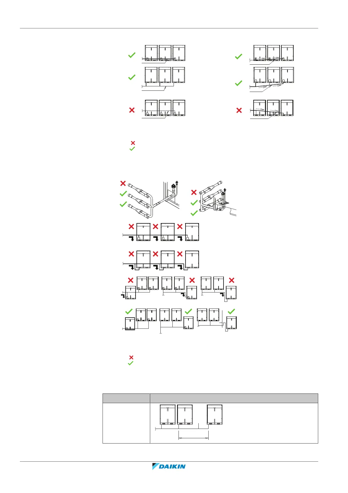
Pattern 1
Pattern 2
a To indoor unit
b Piping between outdoor units
NOT allowed (oil remains in piping)
Allowed
▪ To avoid the risk of oil retention to the outmost outdoor unit, always connect the
stop valve and the piping between outdoor units as shown in the 4 correct
possibilities of the figure below.
a To indoor unit
b Oil collects to the outmost outdoor unit when the system stops
NOT allowed (oil remains in piping)
Allowed
▪ If the piping length between the outdoor units exceeds 2 m, create a rise of
200mm or more in the suction gas line and the high pressure/low pressure gas
line within a length of 2m from the kit.
If Then
≤2m