IM 1131-2 13
Refrigerant Piping
Figure 2: Condenser and Compressor on Same Level, Optional Receiver Installation
Note:
The receiver is bypassed during normal operation.
Receiver notes:
1 The arrangement shown is required if the system
refrigerant charge exceeds the condenser coil pumpdown
capacity.
2 This arrangement is used for head pressure control by
adding a back-flooding valve.
3 When a receiver is not required, the piping from the
condenser outlet to the subcooler inlet is omitted. Flow is
from the subcooling coil directly to the evaporator.
Factory-Mounted Condenser
Units with the standard water-cooled, factory-mounted
condenser are provided with complete refrigerant piping and
full operating refrigerant charge at the factory.
There is a remote possibility on water-cooled units utilizing
low temperature pond or river water as a condensing medium,
and if the water valves leak, that the condenser and liquid line
refrigerant temperature could drop below the equipment room
temperature on the "off" cycle. This problem only arises
during periods when cold water continues to circulate through
the condenser and the unit remains off due to satisfied cooling
load.
If this condition occurs cycle the condenser pump off with the
unit or check the liquid line solenoid valve for proper
operation.
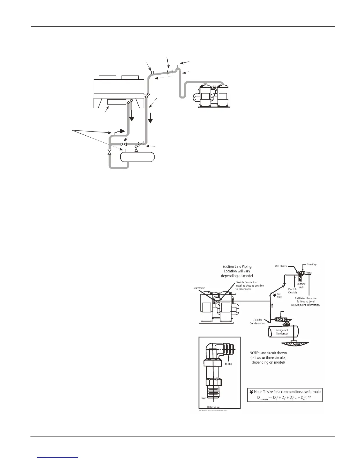
Relief Valve Piping
The ANSI/ASHRAE Standard 15, Safety Standard for
Refrigeration Systems, specifies that pressure relief valves on
vessels containing Group 1 refrigerant (R-410A) "shall
discharge to the atmosphere at a location not less than 15 feet
(4.6 meters) above the adjoining ground level and not less than
20 feet (6.1 meters) from any window, ventilation opening or
exit in any building." The piping must be provided with a rain
cap at the outside terminating point and with a drain at the low
point on the vent piping to prevent water buildup on the
atmospheric side of the relief valve. Also, a flexible pipe
section should be installed in the line to eliminate any piping
stress on the relief valve(s).
The size of the discharge pipe from the pressure relief valve
should not be less than the size of the pressure relief outlet (5/8
in. flare). See Figure 9 for pipe size when combining low side
relief on compressor suction with the condenser relief valve.
NOTE: Fittings should be provided to permit vent piping to be
easily disconnected for inspection or replacement of the relief
valve.
Figure 3: Relief Valve Piping
The relief valve setting is 450 psi (3100 kPa) for water cooled
and 600 psi (4175 kPa) for air-cooled applications.
Relief Va lve
Check Valve
Purge Valve
Relief Valve
it
Valve
Discha rge Line
Re ce ive
Evap.
Valve
Subcooler