IM 1131-2 5
Water Piping
Water Piping
Unit Configuration
WGZ 030DW to 130DW have two refrigerant circuits, two
tandem scroll compressors (total of four), a single two-
circuited brazed plate evaporator, a single two-circuited water-
cooled condenser, interconnecting refrigerant piping and a
control panel with associated sensors and transducers. Models
WGZ 150DW to 200DW have two trio-compressors (total of
6) and a shell-and-tube evaporator.
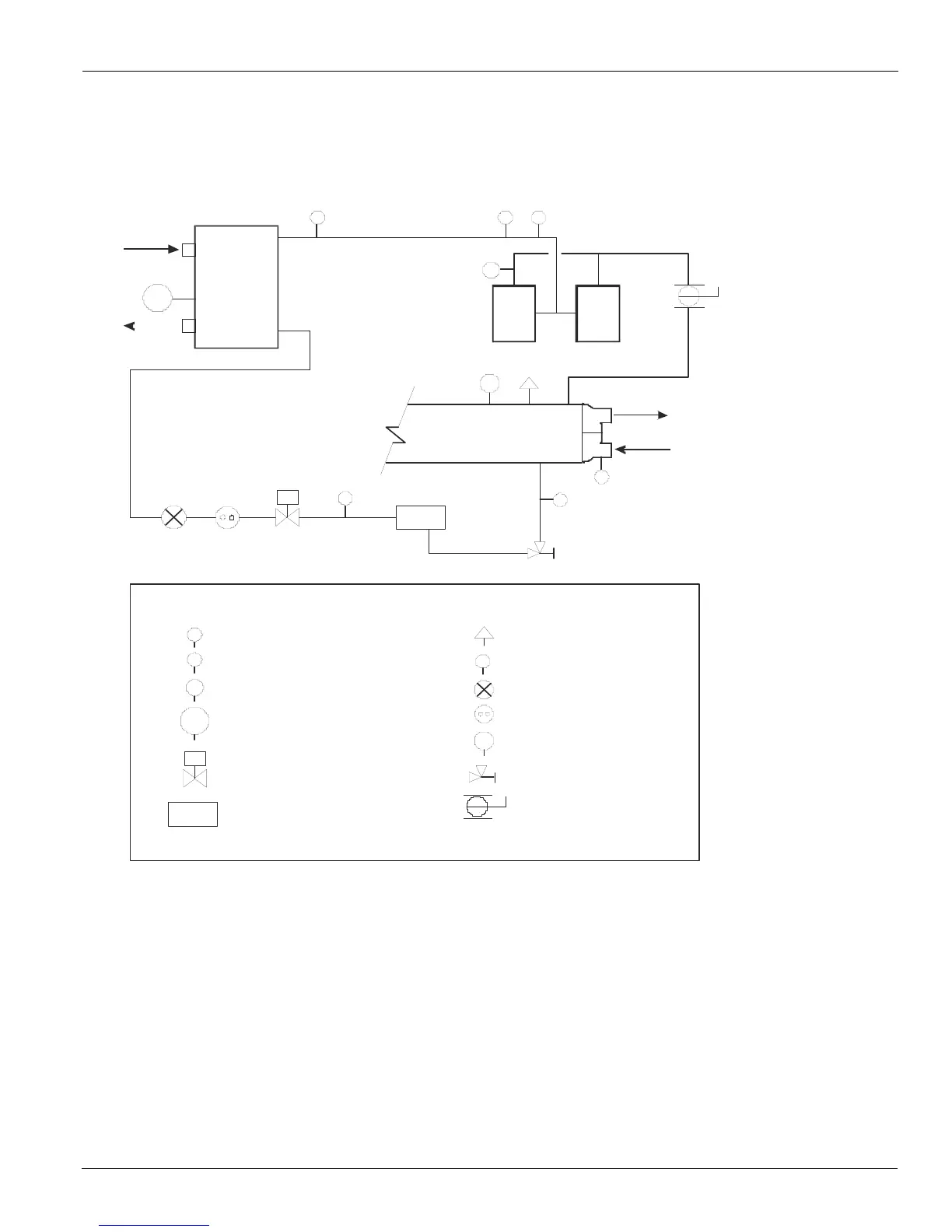
Figure 1: Schematic Piping Diagram (One of Two Circuits for Brazed Plate Evaporators)
Install Vessel Drain Plugs at Start-up
Condensers are drained of water in the factory and are shipped
with the condenser drain plugs in the heads removed and
stored in a bag in the control panel. Be sure to replace plugs
prior to filling the vessel with fluid.
General Piping Guidelines
Due to the variety of piping practices, it is advisable to follow
the recommendations of local authorities for code compliance.
They can supply the installer with the proper building and
safety codes required for a safe and proper installation.
The piping should be designed with a minimum number of
bends and changes in elevation to keep system cost down and
performance up. Other piping design considerations include:
1 All piping should be installed and supported to prevent
the chiller connections from bearing any strain or weight
of the system piping.
2 Vibration eliminators to reduce vibration and noise
transmission to the building.
3 Shutoff valves to isolate the unit from the piping system
during unit servicing.
4 Do not use PVC or CPVC piping for any water lines.
Comp
#2
Comp
#1
Condenser
Condenser
Water
Evaporator
S
F-D
T
S
S
CV
SP
P
1
T
Legend:
Temperature Sensor
Pressure Transducer
Pressure (High Pressure Cutout)
Temperataure Sensor, Leaving
Chilled Water Control
T
T
T
P
P
1
LWT
Relief Valve
Schrader Fitting
Thermal Expansion
Valve
re In dicator
S
CV
Solenoid Valve
F-D Filter-Drier
Angle Valve
Ball Valve
NOTE:
Standard condenser
connections are on
the control panel end.