IOM 1274-3 • CENTRIFUGAL WATER CHILLERS 70 www.DaikinApplied.com
TechResponse@DaikinApplied.com.
Figure 77: Remote Mounting Guidelines for Flow Switch
If needed, the adapter is threaded into the pipe using pipe
mounted onto the adapter using silicone grease. Carefully
apply lubricant to the inside threads and o-ring so temperature
probe does not become coated with lubricant. Torque the
adapter/sensor connection to 18.5 ft/lbs.
Wiring
Refer to wiring diagram in the unit control panel.
controller’s digital input is a DC signal which is supplied
It is required that the AC and DC commons of power be
separated. Contact Chiller Technical Response for alternate
wiring scenarios.
Flow Switch Setup
of 20 cm/s. This value is typically well below the minimum
4 are the calculated gallons per minute (gpm) for Schedule 40
to 300 cm/s.
1.
setup procedure.
2.
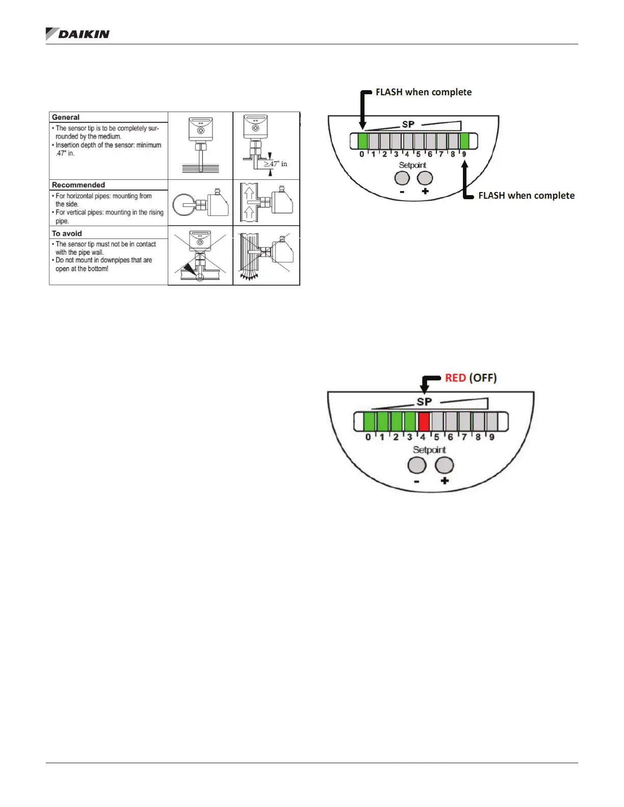
switch. The ‘Teach’ function is initiated by holding down
seconds. During this 15 second period, LEDs ‘0’ and ‘9’
will be lit green. Once the ‘Teach’ function is completed,
2.
Figure 78: Automatic Teach of Setpoint
3. After the ‘Teach’ function is completed and the outer
Figure
79 shows a typical display for this condition. All LEDs
to the left of the SP LED are lit green. The SP LED is
lit RED (or may toggle amber) which indicates that the
Figure 79: Teach Adjustment Complete
point within the desired operating range. Additional ‘manual’
adjustment of set point is required in order to allow for chiller
2.5 cm/s.
4.
shown in Figure 80