www.DaikinApplied.com 71 IOM 1274-3 • CENTRIFUGAL WATER CHILLERS
Table 33: Flow Volume Calculation
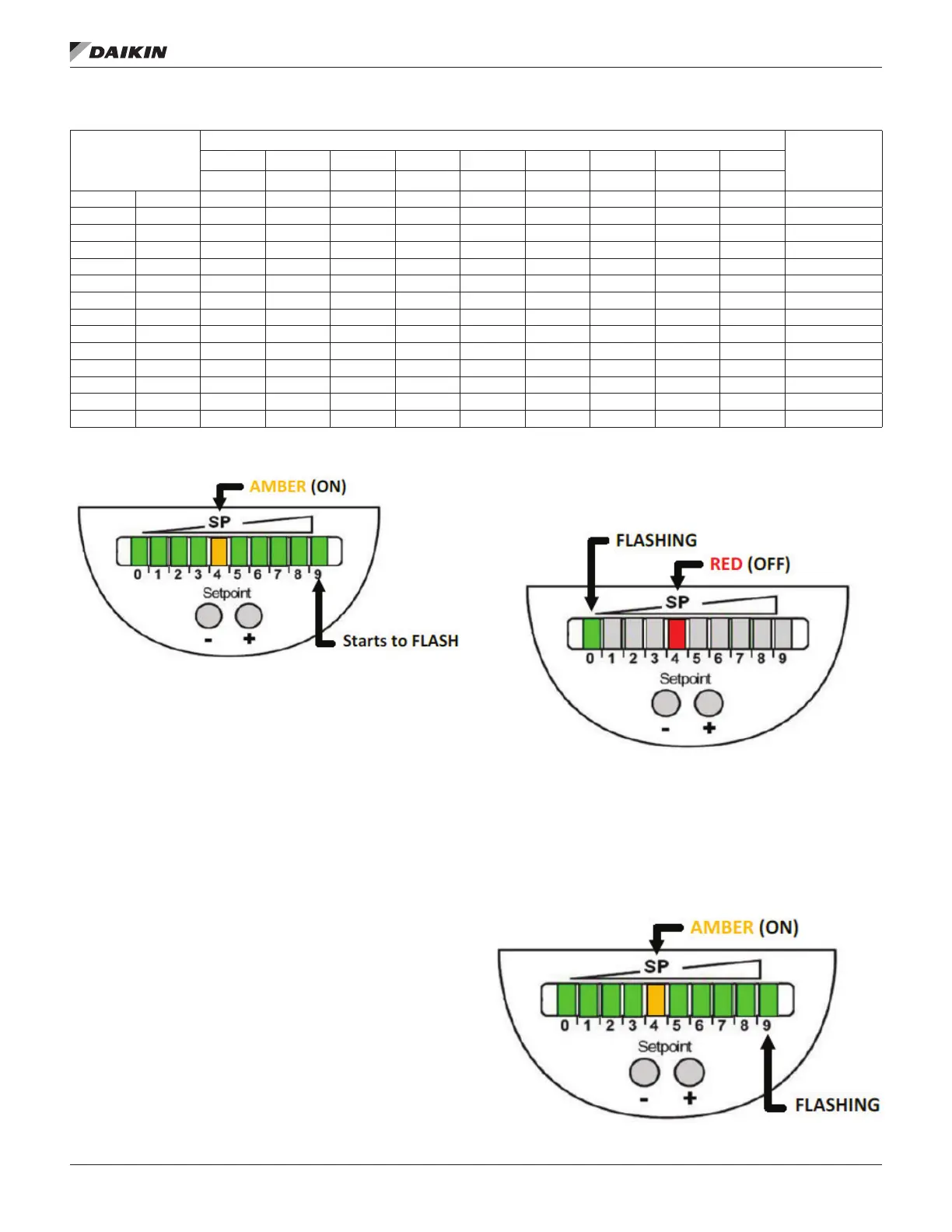
Figure 80: Upper Range of Minimum Flow
5. Once the SP is set, it is recommended that the sensor
be locked to avoid inadvertent readjustment. This can
be performed by pressing both the ‘+’ and ‘-’ buttons
simultaneously for 10 seconds. The indication goes out
momentarily indicating the unit is locked. To unlock, the
same procedure is performed to toggle to unlocked.
NOTE:
a velocity range of 50 cm/s. The window centers on
the set point (SP). For example, if the SP was set to
200 cm/s, then the LED labeled ‘0’ would represent
a velocity of 180 cm/s when lit and the LED labeled 9
would represent a velocity of 230 cm/s when lit.
Each LED represents 5 cm/s, or two presses of the ‘+’
or ‘-’ buttons.
green LEDs light and go out step by step. During this
time, the output is closed. The unit is in the operating
mode.
When making manual adjustments to the set point
(SP), if no button is pressed for 2 seconds, the unit
returns to the operating mode with the newly set
value.
Flow below display range: The SP LED will be lit red and
Figure 81: Display for Flow Below Range
Flow above display range: The SP LED will be lit amber, all
LEDs to the left and right of the SP LED with be green with the
Figure 82: Display for Flow Above Range
Pipe Size
(inch)
Inside Pipe
Diameter
(inch)
US GPM at the velocities indicated below
GPM adjustment
per '+' or '-' key
input
Default
20 cm/sec 30 cm/sec 50 cm/sec 75 cm/sec 100 cm/sec 150 cm/sec 200 cm/sec 250 cm/sec 300 cm/sec
2 2.06 6.86 10.3 17.2 25.7 34.3 51.5 68.6 85.8 102.9 1.72
2.5 2.46 9.79 14.7 24.5 36.7 49.0 73.4 97.9 122.4 146.9 2.42
3 3.07 15.1 22.7 37.8 56.7 75.6 113.4 151.2 189.0 226.8 3.78
3.5 3.55 20.2 30.3 50.6 75.8 101.1 151.7 202.2 252.8 303.3 5.06
4 4.03 26.0 39.1 65.1 97.7 130.2 195.3 260.4 325.5 390.5 6.51
5 5.05 40.9 61.4 102.3 153.5 204.6 306.9 409.2 511.5 613.7 10.2
6 6.07 59.1 88.6 147.7 221.6 295.5 443.2 590.9 738.7 886.3 14.8
8 7.98 102.3 153.5 255.8 383.7 511.6 767.5 1023.3 1279.1 1534.7 25.6
10 10.02 161.3 241.9 403.2 604.8 806.5 1209.7 1612.9 2016.2 2419.1 39.0
12 11.94 229.0 343.4 572.4 858.6 1144.7 1717.1 2289.5 2861.9 3433.8 57.2
14 13.13 276.8 415.2 692.0 1037.9 1383.9 2075.9 2767.8 3459.8 4151.3 69.2
16 15.00 361.5 542.2 903.6 1355.5 1807.3 2710.9 3614.6 4518.2 5421.2 90.4
18 16.88 457.5 686.3 1143.8 1715.7 2287.6 3431.4 4575.2 5719.0 6862.1 114.4
20 18.81 572.4 853.0 1421.6 2132.4 2843.2 4264.8 5686.4 7108.0 8528.6 142.2