Do you have a question about the Danaher Motion SERVOSTAR CD-LITE and is the answer not in the manual?
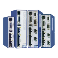
Details the extensive features of the SERVOSTAR CD-Lite amplifier for motion control applications.
Lists key capabilities like digital current loop, velocity loop, current ratings, and easy setup.
Highlights the amplifier's durability with isolated electronics and comprehensive fault protection.
Describes various feedback types supported by the SERVOSTAR CD-Lite, including encoders and resolvers.
Explains how to configure the amplifier using MOTIONLINK and Personality Modules for ease of setup.
Details the features and capabilities of the MOTIONLINK software for setup, monitoring, and troubleshooting.
Outlines tools within MOTIONLINK for monitoring drive operation and diagnosing issues.
Covers watchdog faults, speed/current protection, thermal protection, and limit switch detection.
Provides general information including enabling/disabling features, firmware memory, and torque angle control.
Compares the SERVOSTAR CD-Lite features and specifications with the standard SERVOSTAR CD.
Lists the necessary hardware and software requirements for running the MOTIONLINK software.
Specifies the serial communication settings required for connecting to the SERVOSTAR CD-Lite.
Illustrates the data flow between a PC and the SERVOSTAR CD-Lite, explaining parameter handling.
Provides step-by-step instructions for installing the MOTIONLINK software on a PC.
Explains the different methods for configuring the drive using the MOTIONLINK software.
Describes the step-by-step Startup Wizard for initial drive configuration and parameter setup.
Details how to set drive voltage parameters and monitor DIP switch settings via the Drive button.
Explains how to select and download motor parameters from the MOTIONLINK motor database.
Guides on selecting operational modes and tuning parameters like bandwidth and filtering for specific applications.
Describes the main interface of MOTIONLINK, accessed after exiting the Startup Wizard for corrections.
Explains how to restore the drive to its original factory variable parameters.
Details the process of restoring custom parameters from an .SSV file into the drive.
Describes using Terminal Mode for direct monitoring and modification of drive variables and commands.
Covers the initial power-up sequence, self-tests, and basic configuration verification.
Explains the conditions and flags required to enable the drive and apply power to the motor.
Details the incremental encoder feedback signal, its resolution, and associated circuits.
Lists the technical specifications for encoder requirements, including signal type, voltage, and frequency.
Provides recommendations and considerations for encoder cable lengths to ensure reliable signal transmission.
Explains how SERVOSTAR systems achieve high resolution and accuracy with encoder feedback.
Describes how the drive uses A/B/Z/Hall signals for commutation and angle calculation.
Explains the operation of A/B/Hall feedback signals for commutation and angle calculation.
Discusses the use of resolver feedback for motor shaft position and its characteristics.
Explains how the drive obtains absolute position from the resolver's sine and cosine signals.
Lists the technical specifications for resolver feedback, including transformation ratio and modulation frequency.
Provides guidance on cable types and lengths for resolver feedback systems.
Details how SERVOSTAR calculates motor velocity and its resolution capabilities with resolver feedback.
Lists the inaccuracy contributions of R/D converter components to overall system accuracy.
Summarizes the accuracy specifications for resolver feedback systems in arc minutes.
Explains how hall signals are used for commutation with sinus commutation.
Details the hall signal states and their relation to phase and disconnect for six-step commutation.
Describes the encoder equivalent output signals and their use for position feedback.
Discusses resolver system output signals, resolution, and index pulse placement.
Explains the encoder system output signal, scaling, and frequency limits.
Describes the different drive states like Power-up, Steady State, Flashing State, and Momentary Fault.
Details the appearance of the seven-segment indicator and the meaning of its display segments.
Explains the meaning of the decimal point on the Status Display, indicating drive enable status.
Describes the drive status (OFF, ON, Flashing) and what each state signifies.
Explains the different operating modes (OPMODE=1 Velocity, OPMODE=3 Torque) of the SERVOSTAR CD-Lite.
Discusses the Input/Output features of the C3 connector, excluding the Thermostat input.
Details the analog input for velocity or torque command, including scaling and offset adjustments.
Explains the function of the opto-isolated Remote Enable input for hardware drive enable.
Describes the relay output used for ‘Drive Ready’ or ‘Drive Up’ indication and its configuration.
Details the two limit switches available in Velocity mode for CW and CCW direction control.
Explains the use of the ±10V, 8-bit analog output for monitoring and tuning purposes.
Describes the fixed digital output that indicates regular operation or Foldback mode.
Introduces the servo control loops, their characteristics, and configuration methods.
Details the embedded controller and DSP controller, their operating system, and firmware.
Describes the digital, high-bandwidth current loop, its function, and PWM signal generation.
Explains the commutation loop's role in converting current commands to three-phase sine waves using Torque Angle Advance.
Details the digital velocity loop, its function in regulating motor speed, and its filtering algorithm.
Introduces the torque loop configuration and internal variables for system operation analysis.
Describes the common configuration of the CD-Lite in analog torque loop mode and the signal processing path.
Explains how current feedback is sampled using closed-loop hall sampling for current regulation.
Introduces the two types of FoldBack protection for the motor and the drive.
Details the Drive Foldback algorithm that monitors and reduces current to prevent damage.
Explains how the SERVOSTAR CD-Lite communicates error codes and the three severity levels of errors.
Lists fatal error codes, their status display, messages, possible causes, and severity.
Lists non-fatal error codes, their status display, messages, possible causes, and severity.
Details faults indicated only by status display codes, not text messages.
Explains how the microprocessor monitors components and logs faults, including common fault types.
Describes power stage faults like short-circuit, transistor failure, and overcurrent.
Explains faults related to out-of-tolerance ±12 VDC analog supply values.
Details the overspeed fault condition when motor speed exceeds the VOSPD limit.
Describes the fault when the drive cannot design a compensator, indicated by a flashing minus sign.
Explains faults detected in RAM, EPROM, and EEPROM during initialization.
Discusses watchdog failures that indicate serious problems and cause the drive to halt.
Provides a step-by-step guide for upgrading the SERVOSTAR CD-Lite firmware using the Ignite CD-Lite application.
States the required firmware version for using the Personality Module with the CD-LITE.
Explains how to connect and use the Personality Module, including its switches and LED indicator.
Details how errors are displayed on the CD-Lite's 7-segment display during module operations.
Presents a schematic diagram illustrating the Personality Module's connections and functions.
Provides the part number for ordering the Personality Module.
Details the pinouts for motor power connections across different Kollmorgen motor series.
Shows the pinout for connecting resolvers to the SERVOSTAR drive for various motor types.
Provides detailed pinout information for LE encoder connections to SERVOSTAR drives.
Guides through an example setup, focusing on configuring the CD-Lite for a GOLDLINE motor in Torque Mode.
Step-by-step instructions on starting MOTIONLINK and initiating the motor configuration process.
Details selecting the motor family, model, and downloading parameters to the drive.
Guides on selecting the encoder type and resolution for feedback configuration.
Explains how to initialize the encoder using the Enc Init tab and enter resolution values.
Describes setting the operation mode to Analog Torque and selecting Analog Input.
Details the Analog Input configuration window for setting offset, deadband, and filter.
Explains how to use the Zero Input function for the ANZERO procedure and change axis state.
Guides on changing the axis state from Disable to Enable and setting Analog Offset.
Discusses using linear motors with the CD-LITE and the need for parameter conversion.
Provides formulas and guidelines for calculating CD-Lite parameters for linear motors.
Explains the support for PTC and NTC motor thermostats and their fault state conditions.
| Number of Axes | 1 |
|---|---|
| Control Modes | Torque, Velocity, Position |
| Communication | CANopen |
| Communication Interface | CANopen |
| Feedback | Incremental Encoder |
| Protection Features | Overvoltage, Overcurrent, Overtemperature |