33
Fahrzeug-/Funktionsdecoder ab Firmware-Version 1.11
33
Locomotive/Locomotive function decoder from firmware version 3.12
5 In case your locomotive is equipped with an interface according to NEM 652, you need for FH18A the connecting
adapter N18-G-2. It has already the appropriate connection cables for this socket with an 8 pin plug. The decoder can
be inserted into the interface without any problem now.
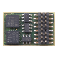
6 In case your locomotive is equipped with an 18 pin interface (Next18), you can plug FH18A directly into the interface
without any problem.
7 In case your locomotive has no interface socket, you need for FH18A either connecting adapter N18-K-3 without SUSI)
or N18-G-3 ((with SUSI) for an idividual wiring.
8 Connecting adapter N18-K-0 (without SUSI) or N18-G-0 (with SUSI) should be used only by experienced model
railroaders, as the connection wires must be soldered directly onto the respective adapter
There are following variants to connect the locomotive function decoder FH22A:
9
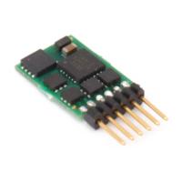
In case your locomotive is equipped with a 22 pin interface (PluX22), use decoder FH22A-
4. It has already the appropriate
plug for this socket. The decoder can be inserted into the interface without any problem now.
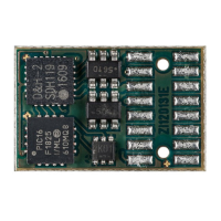
10 In case your locomotive has no interface socket, use decoder FH22A-4 together with the adapter P22-3 for individual
wiring.
11 Decoder FH22A-4 together with the adapter P22-0 should be used only by experienced model railroaders, as the
connection wires must be soldered directly onto the adapter.
For above variants 2, 7 and 10 connect the decoder or adapter wires according to the following diagram (see also the chart
on the following page):
red wire ........................ with the right track wire
black wire ..................... with the left track wire
white wire ..................... with the front light in driving direction
yellow wire ................... with the rear light in driving direction
green wire .................... function output AUX1
violet wire ..................... function output AUX2
BA DH engl FW3_12 Druck.indd 33BA DH engl FW3_12 Druck.indd 33 10.05.21 14:2710.05.21 14:27